A device for measuring complex permittivity of microwave closed resonator

A closed resonant cavity, complex permittivity technology, applied in measuring devices, measuring electrical variables, measuring resistance/reactance/impedance, etc. The effect of eliminating radiation loss, overcoming large radiation loss and high accuracy is achieved

Active Publication Date: 2018-01-23
METROLOGY & MEASUREMENT CENT OF CHINA ACADEMY OF ENG PHYSICS
View PDF4 Cites 0 Cited by
  • Summary
  • Abstract
  • Description
  • Claims
  • Application Information

AI Technical Summary

Problems solved by technology

[0003] The existing resonant cavity method has some shortcomings. For example, the dielectric resonator method specified in the national standard GB7265.2-87 uses an open resonant cavity, which needs to rely on dielectric materials to bind the electromagnetic field, so it is mainly used to test dielectric Materials with a high constant value, when the dielectric constant value of the tested material is low, the binding effect on the electromagnetic field is too small to complete the test
Although the high-Q cavity method stipulated in the national standard GB / T5597-1999 uses a closed resonant cavity, the sample is in direct contact with the inner surface of the resonant cavity, which brings a large metal surface current loss and affects the measurement of the imaginary part of the dielectric constant.
The perturbation method needs to make the sample material to be tested into a thin rod. The small size of the sample and the use of approximate calculations result in low measurement accuracy.
The quasi-cavity method is mainly used in the millimeter-wave band with higher frequencies, and it is difficult to measure in the microwave frequency band

Method used


Image

  • A device for measuring complex permittivity of microwave closed resonator
  • A device for measuring complex permittivity of microwave closed resonator
  • A device for measuring complex permittivity of microwave closed resonator

Examples


Embodiment Construction

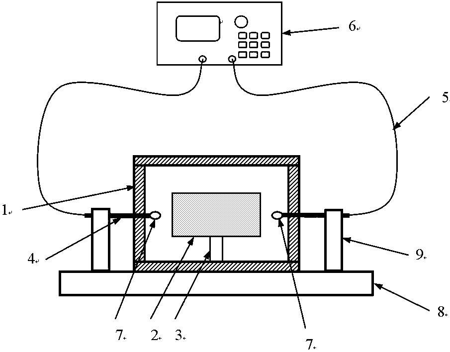
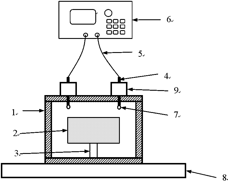
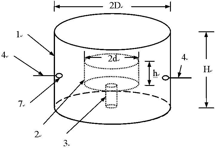
[0022] In the microwave closed resonant cavity complex permittivity measuring device of the present invention, the measured dielectric material is placed in the closed resonant cavity, and the supporting column is placed in the center of the cavity, and the electromagnetic field inside the cavity is controlled by two coupling probes. For coupling, an external vector network analyzer with sweep frequency measurement function is used to measure the microwave scattering parameters of the closed resonant cavity. According to the measured resonant frequency and the corresponding quality factor Q value, the electromagnetic field distribution in the cavity and the corresponding electromagnetic field are calculated by the mode matching method. Mode, metal wall current loss value, and finally get the exact solution of the complex dielectric constant of the dielectric material. test system such as figure 1 As shown, it is mainly composed of closed resonant cavity, tested material, suppo...


PUM


Abstract

The invention provides a microwave closed resonator complex dielectric constant measuring device. It contains a closed resonant cavity, a measured dielectric material, a support column, a coupling probe, a test cable, a vector network analyzer, a base, and a coupling probe holder; it is characterized in that the measured dielectric material is placed inside the closed resonant cavity On the supporting column, the coupling probe extends into the closed resonant cavity through the coupling hole, and the test cable is connected to the vector network analyzer. The closed resonant cavity is fixedly placed in the middle of the base, and the coupling probe holder is placed on the base and They are arranged on both sides of the closed resonant cavity, and the coupling probes are fixed on the coupling probe holders. The invention is suitable for the measurement of low-loss and high-loss dielectric materials.

Description

technical field [0001] The invention belongs to the technical field of microwave testing, and in particular relates to a closed resonant cavity measuring device, which is used to accurately measure the complex dielectric constant of microwave dielectric materials. Background technique [0002] Microwave dielectric materials are widely used in aerospace, military equipment, electronic communication and other fields, and the dielectric constant is the most important electrical parameter of dielectric materials. The accurate measurement of dielectric constant is very important for the development and development of various new dielectric materials. Practical application is of great significance. The dielectric constant measurement methods are mainly divided into two categories, the first is the transmission line method, the second is the resonant cavity method, and the resonant cavity method can be divided into dielectric resonator method, high Q cavity method, perturbation cav...

Claims


Application Information

Patent Timeline
Patent Type & Authority Patents(China)
IPC IPC(8): G01R27/26
Inventor 王益张翠翠王建忠魏竹
Owner METROLOGY & MEASUREMENT CENT OF CHINA ACADEMY OF ENG PHYSICS
Why Eureka
Try Eureka