An Error Compensation Control Method for a Stacked Workbench

A control method and error compensation technology, applied in the field of machine tool error compensation, can solve problems such as affecting the machining accuracy of workpieces, and achieve the effect of improving machining accuracy and high modeling accuracy

Active Publication Date: 2018-01-23
ANHUI UNIV OF SCI & TECH
View PDF5 Cites 0 Cited by
  • Summary
  • Abstract
  • Description
  • Claims
  • Application Information

AI Technical Summary

Problems solved by technology

Therefore, the comprehensive error of the two guide rails in each direction will directly affect the machining accuracy of the workpiece

Method used


Image

  • An Error Compensation Control Method for a Stacked Workbench
  • An Error Compensation Control Method for a Stacked Workbench
  • An Error Compensation Control Method for a Stacked Workbench

Examples


Embodiment Construction

[0046] In order to make the purpose, technical solutions and advantages of the embodiments of the present invention clearer, the technical solutions in the embodiments of the present invention will be clearly and completely described below in conjunction with the drawings in the embodiments of the present invention. Obviously, the described embodiments It is a part of embodiments of the present invention, but not all embodiments. Based on the embodiments of the present invention, all other embodiments obtained by persons of ordinary skill in the art without creative efforts fall within the protection scope of the present invention.

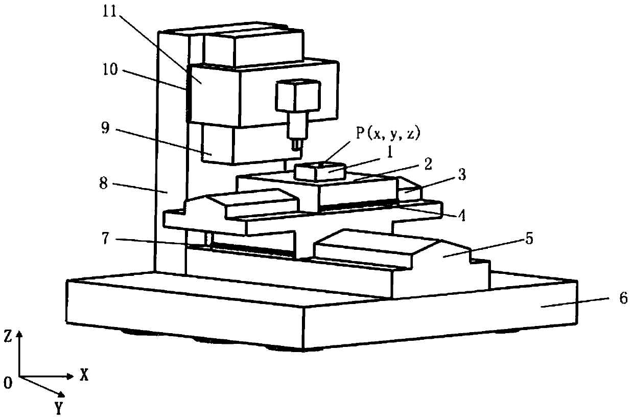
[0047] figure 1 It is a structural diagram of a stacked workbench. The main body of the machine tool includes a bed 6, a worktable 2, an X-axis guide rail 3, an X-direction grating scale 4, a Y-axis guide rail 5, a Y-direction grating scale 7, a column 8, a Z-axis guide rail 9, and a Z-axis guide rail 9. Direction grating scale 10, main shaft box...


PUM


Abstract

The present invention discloses an error compensation control method for a stack worktable. The method is applied to the technical field of error compensation of machine tools and comprises: analyzing an Abbe error in the Y direction of a machining point caused by a swing angle and a pitch angle of a Y-axis guide rail of a stackable worktable, and building an Abbe error model; analyzing correlation and compensatory impacts of an angular error of the Y-axis guide rail of the stackable worktable on an angular error of an X-axis guide rail; building an Abbe error model in the X direction of the machining point under the combined effects of the angular error of the X-axis guide rail and the angular error of the Y-axis guide rail; and applying the model to perform compensation control on a two-dimensional Abbe error of unidirectional motion of the stackable worktable. The model is higher in accuracy, conforms better to the actual operating state of the worktable, and provides the basis for further error measurement and error compensation, thereby effectively improving machining accuracy of machine tools.

Description

technical field [0001] The invention relates to the technical field of machine tool error compensation, in particular to an error compensation control method for stacked workbenches. Background technique [0002] At present, most machine tools adopt a stacked structure, that is, the slide plates in the X and Y directions are superimposed and installed on the bed, and each direction is supported by two guide rails to move in one direction. The workbench is installed on the sliding plate, and the workpiece is placed in the middle of the workbench for positioning. Therefore, the comprehensive error of the two guide rails in each direction will directly affect the machining accuracy of the workpiece. [0003] The error of the guide rail system in the geometric error of the machine tool is not only related to the quality of the guide rail system itself, but also the three-dimensional thermal deformation and force deformation error of the bed will be coupled to the guide rail sys...

Claims


Application Information

Patent Timeline
Patent Type & Authority Patents(China)
IPC IPC(8): G06F17/50
Inventor 杨洪涛喻曹丰费业泰吴天凤查小娜
Owner ANHUI UNIV OF SCI & TECH
Why Eureka
Try Eureka