Wearable shunt-fed antenna

An antenna and feeder technology, which is applied in the field of wearable and feeder antennas, can solve the problems of unreachable S-parameters, decreased antenna signal strength, and unfavorable integration and manufacturing.

Active Publication Date: 2015-10-07
LANZHOU UNIVERSITY
View PDF4 Cites 2 Cited by
  • Summary
  • Abstract
  • Description
  • Claims
  • Application Information

AI Technical Summary

Problems solved by technology

[0002] The application of human body-centered network communication technology in sports, mining, navigation, tracking, medical treatment, etc., has made wearable antennas get a lot of attention, the most important of which is the negative impact of the human body on the performa

Method used


Image

  • Wearable shunt-fed antenna
  • Wearable shunt-fed antenna
  • Wearable shunt-fed antenna

Examples


Embodiment 1

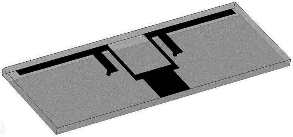
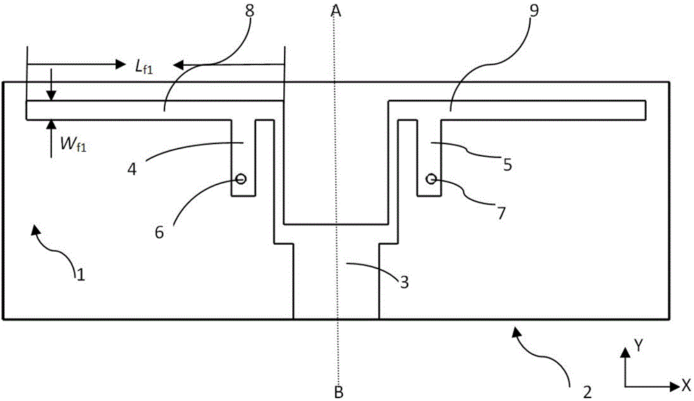
[0032] On the basis of the above calculations, the attached figure 1 Shown basic structure of the present invention, the orthographic projection schematic diagram of its main view position is referring to attached figure 2 shown.

[0033] When constructing this 2.4GHz wearable planar inverted-F parallel-fed antenna, according to the formulas (1) and (2), the length and width of the F-shaped radiating element and the radius of the short-circuit probe are preliminarily calculated, and the optimized An antenna with a center frequency of 2.4GHz is designed. See attached figure 2 , wherein 1 is a dielectric substrate, which is made of wearable ordinary fabric; 2 is the ground of the antenna, which is made of conductive fabric material. The ground is on the lower surface of the dielectric substrate, and it is 2-4 millimeters narrower than the width of the dielectric substrate. In the embodiment of the invention, the ground is 3 mm narrower than the width of the dielectric subst...

Embodiment 2

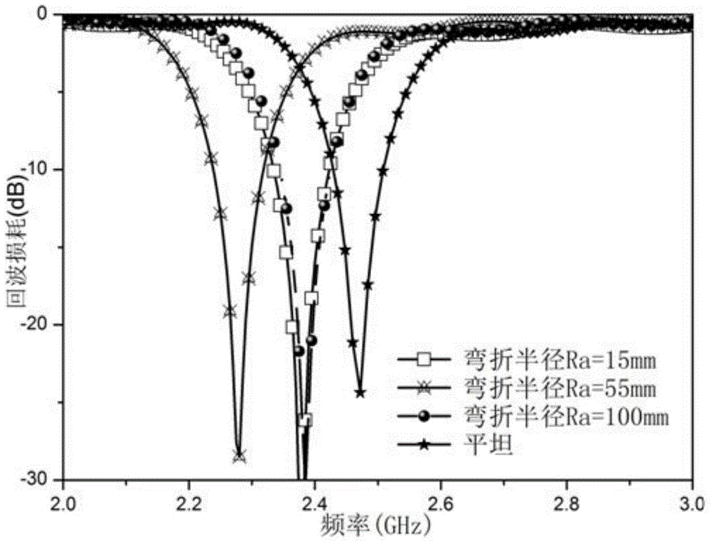
[0035] In order to confirm the correctness of the antenna of the present invention, the antenna has been simulated and the finished product has been measured, the results can be found in image 3 and Figure 4 .

[0036] In the embodiment of the present invention, thin felt is used for the dielectric substrate, and the metallized nylon conductive fabric Roller-Dell-CR of shield company is used for other parts, and the surface resistivity is less than 0.009 ohm. The frequency characteristic of this embodiment is the magnitude of the return loss (dB), in the appended image 3 And attached Figure 4 The "flat" in the figure represents the return loss simulated and measured in the actual environment without any processing of the antenna. In the figure: the abscissa represents the frequency, the unit is GHz, and the ordinate represents the magnitude of the return loss, the unit is dB , it can be seen from the figure that the center frequency of the invented antenna simulation an...

Embodiment 3

[0039] This example is for figure 1 The structure shown is simulated and measured by human body wearing to determine the impact of the wearable antenna of the present invention on the human body and to understand the near-body characteristics of the antenna of the present invention. During the simulation, the human body is approximated as a cylinder, from the outside to the inside, which are skin, fat, muscle, and bone. The return loss of the antenna was measured on the clothes and the arm respectively.

[0040] For simulation and measurement results see Figure 6 , the radius of the cylindrical human body is 40mm during the simulation, the abscissa represents the frequency, the unit is GHz, and the ordinate represents the amplitude of the return loss, the unit is dB. When the antenna is simulated close to the body, the center frequency of the antenna moves to the left. According to the measurement results, whether the antenna is placed directly on the arm or separated from ...


PUM

PropertyMeasurementUnit
Widthaaaaaaaaaa
Heightaaaaaaaaaa
Heightaaaaaaaaaa

Abstract

The invention discloses a wearable shunt-fed antenna which is applied to a 2.4GHz frequency band and is of an inverse-F-shaped structure. The antenna of the invention includes a dielectric substrate composed of wearable common fabrics, a ground surface which is arranged at the lower surface of the dielectric substrate and is composed of conductive fabric materials, as well as monopole radiating units and a feeder line which are arranged at the upper surface of the dielectric substrate; the monopole radiating units are symmetrically arranged at two sides of the feeder line which is vertical to the monopole radiating units; two sides of the feeder line are symmetrically provided with short-circuiting microstrip lines for connecting short-circuiting probes and the monopole radiating units; and the short-circuiting microstrip lines are vertical to the monopole radiating units. The wearable shunt-fed antenna has the advantages of high gain of an array antenna and stable frequency of a plane inverse-F-shaped antenna. The wearable shunt-fed antenna can be suitably adopted as a wearable antenna.

Description

technical field [0001] The invention relates to a wearable parallel-feed antenna applied in the 2.4GHz frequency band, in particular to a wearable parallel-feed antenna with an inverted-F structure. Background technique [0002] The application of human body-centered network communication technology in sports, mining, navigation, tracking, medical treatment, etc., has made wearable antennas get a lot of attention, the most important of which is the negative impact of the human body on the performance of the antenna, making the radiation of the antenna The signal strength drops, the center frequency shifts, and the S parameters fail to meet the required requirements. At the same time, the size of the antenna is large, which is not conducive to integration and manufacturing. How to greatly reduce the size and improve the stability of parameters while improving the near-body characteristics of the antenna is the technical focus of wearable antenna design. [0003] Compared wit...

Claims


Application Information

Patent Timeline
IPC IPC(8): H01Q1/36H01Q1/38H01Q1/22H01Q13/08
Inventor 胡斌贺乐乐高国平赵晋宁田晓龙
Owner LANZHOU UNIVERSITY
Why Eureka
Try Eureka