Rechargeable battery cell and rechargeable battery module

A battery module, battery technology, applied in the directions of large flat cells/batteries, small-sized cells/batteries, batteries, etc., can solve problems such as short circuits, hindering tool accessibility, and inability to achieve electrical insulation of connecting electrodes.

Active Publication Date: 2015-10-07
ROBERT BOSCH GMBH +1
View PDF4 Cites 0 Cited by
  • Summary
  • Abstract
  • Description
  • Claims
  • Application Information

AI Technical Summary

Problems solved by technology

As a result, reliable electrical insulation between connection electrodes cannot be achieved.
Furthermore, during the assembly of a correspondingly configured battery module, an unintentional short circuit may result if an electrically conductive t

Method used


Image

  • Rechargeable battery cell and rechargeable battery module
  • Rechargeable battery cell and rechargeable battery module
  • Rechargeable battery cell and rechargeable battery module

Examples


Embodiment Construction

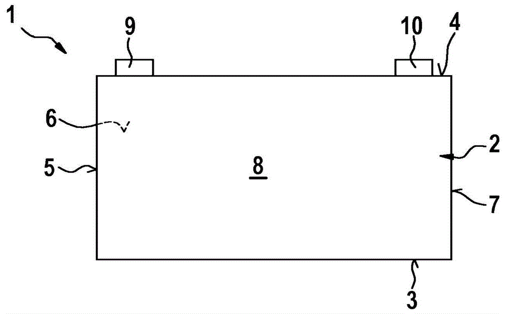
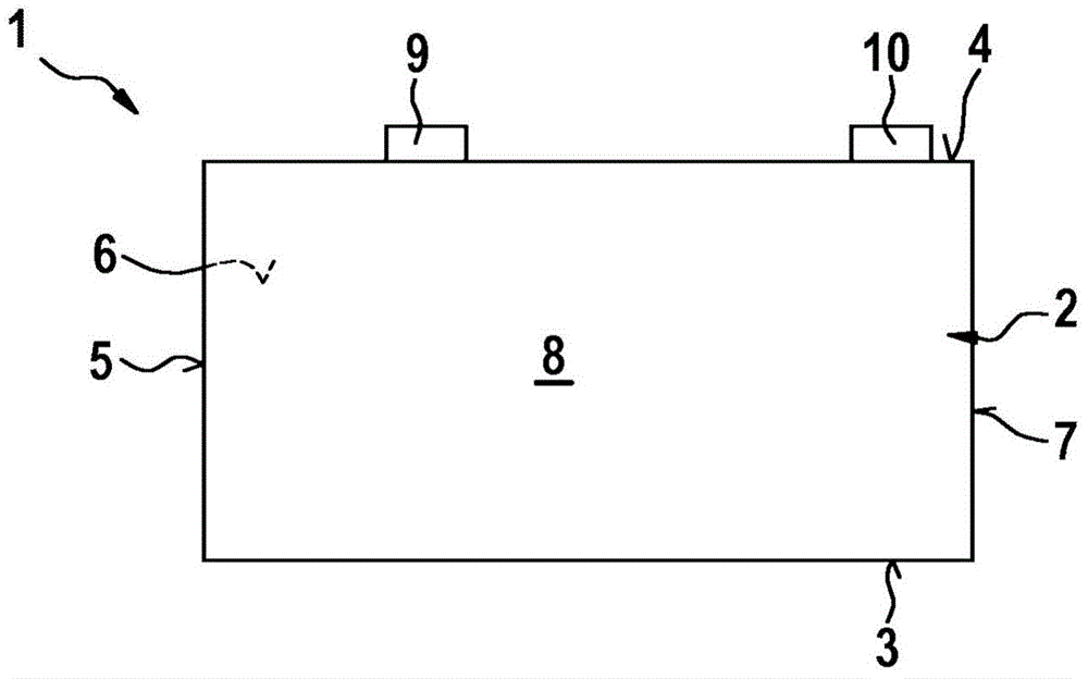
[0020] figure 1 The longitudinal sides of a conventional battery cell 1 are schematically shown. The battery cell 1 comprises a cell housing 2 having a base 3 , a cover 4 and side walls 5 to 8 connecting the base 3 to the cover 4 . The cell housing 2 is formed in the form of a square in the battery cell 1 . The base 3 , the cover 4 and the side walls 5 to 8 are thus formed in a rectangular shape.

[0021] The cover part 4 is designed to extend in the longitudinal direction and has two openings, not further shown, arranged along its longitudinal extension parallel to the drawing plane and two ends arranged opposite one another with reference to its longitudinal extension, wherein the second one end at figure 1 and figure 2 Arranged at the end of the cover 4 shown on the left, and the second end at figure 1 and figure 2 is arranged at the end of the cover part 4 shown on the right. The connecting electrodes 9 or 10 are each guided through one of the openings. The conne...


PUM


Abstract

The invention relates to a rechargeable battery cell (1) having a cell housing (2) that has a bottom (3), a top (4) and lateral walls (5, 6, 7, 8) connecting the bottom (3) to the top (4), wherein the top (4) is elongate and has two openings provided along its longitudinal extension and, with regard to its longitudinal extension, two ends that are opposite each other, wherein a positive electrical terminal (9, 10) of the rechargeable battery cell (1) passes through one opening and a negative electrical terminal (9, 10) of the rechargeable battery cell (1) passes through the other opening., wherein said electrical terminals (9, 10) project by a predefinable amount from the upper side of the top (4) remote from the inside of the cell housing (2), a first electrical terminal (9) of the electrical terminals (9, 10) being situated closer to a first end of the two ends of the top (4) than to a second end of the two ends of the top (4), and a second electrical terminal (10) of the electrical terminals (9, 10) being situated closer to the second end of the top (4) than to the first end of the top (4), characterized in that the distance between the first electrical terminal (9) and the first end of the top (4) is larger than the distance between the second electrical terminal (10) and the second end of the top (4).

Description

technical field [0001] The invention relates to a battery cell and a battery module. Background technique [0002] In electrically driven motor vehicles, in particular electric vehicles and hybrid vehicles, the battery is used to supply the electric drive of the motor vehicle with electrical energy. Batteries of this type are usually formed by joining a number of battery modules connected in series. Each battery module usually has a plurality of battery cells connected in series, which are usually based on lithium. Each battery cell includes a cell housing and an electrochemical cell disposed in the cell housing. Arranged on one side of the cell housing are connecting electrodes via which electrical energy can be extracted from the battery cells or via which electrical energy can be supplied to the battery cells. The connecting electrodes of the battery cells are made, for example, of aluminum or copper. The connecting electrodes can be made of the same material or of di...

Claims


Application Information

Patent Timeline
IPC IPC(8): H01M2/30H01M2/10H01M2/04H01M10/04H01M2/20H01M50/147H01M50/209H01M50/278H01M50/507H01M50/51H01M50/55H01M50/553
CPCH01M2/1077H01M2/043H01M2/0473H01M2/206H01M2/30H01M2/34H01M10/0413H01M2220/20Y02E60/10H01M50/15H01M50/147Y02P70/50H01M50/507H01M50/278H01M50/209H01M50/51H01M50/55H01M50/553
Inventor M·科尔贝格尔J·比德特
Owner ROBERT BOSCH GMBH
Why Eureka
Try Eureka