Direct drive permanent magnet wind power heating system
A permanent magnet and wind power technology, which is applied in the direction of wind power generators, wind power motor combinations, motors, etc., can solve the problems of low conversion efficiency, low power density, and low reliability, and achieve high conversion efficiency, high power density, and high reliability Effect
- Summary
- Abstract
- Description
- Claims
- Application Information
AI Technical Summary
Problems solved by technology
Method used
Image
Examples
specific Embodiment approach 1
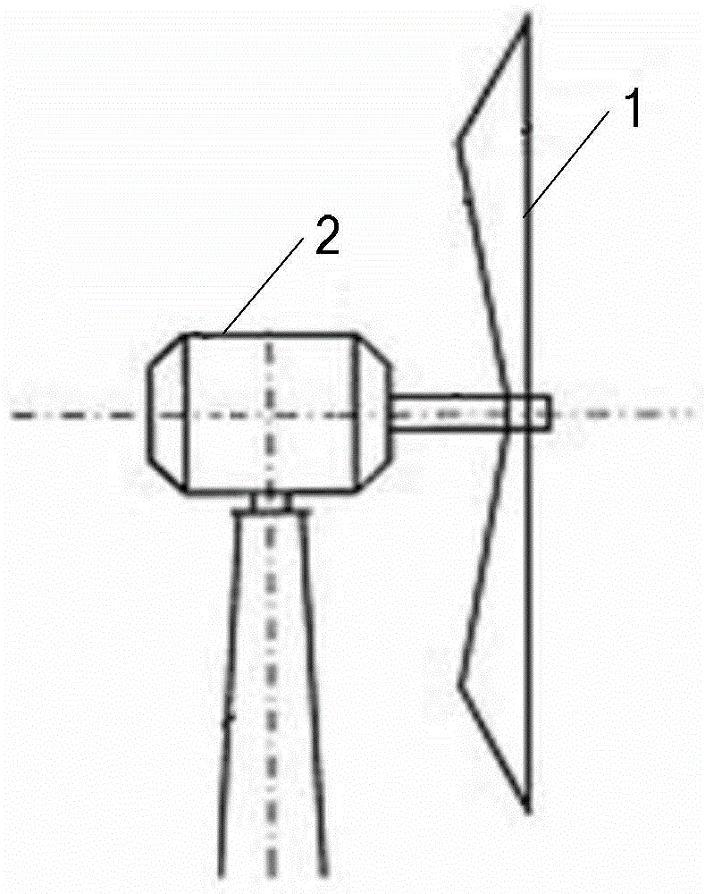
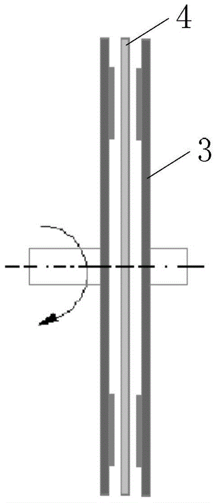
[0049] Specific implementation mode one: see figure 1 and 2 Describe this embodiment, a kind of direct drive permanent magnet wind power heating system described in this embodiment, it comprises wind turbine 1 and heater 2, the output shaft of wind turbine 1 is connected with the rotor shaft of heater 2 in rotation,
[0050] The heater 2 comprises a stator and a rotor, an air gap is formed between the stator and the rotor,
[0051] The stator is composed of n stator units 4, and the rotor is composed of n+1 rotor units 3, where n is a natural number;
[0052] There is an air gap between the rotor unit 3 and the stator unit 4;
[0053] The rotor unit 3 is a disc rotor unit, the stator unit 4 is a disc stator unit,
[0054] n+1 disk-shaped rotor units and n disk-shaped stator units are arranged alternately along the axial direction,
[0055] The n stator units 4 are all fixed on the stator bracket, and the n+1 rotor units 3 are all fixed on the rotor shaft.
specific Embodiment approach 2
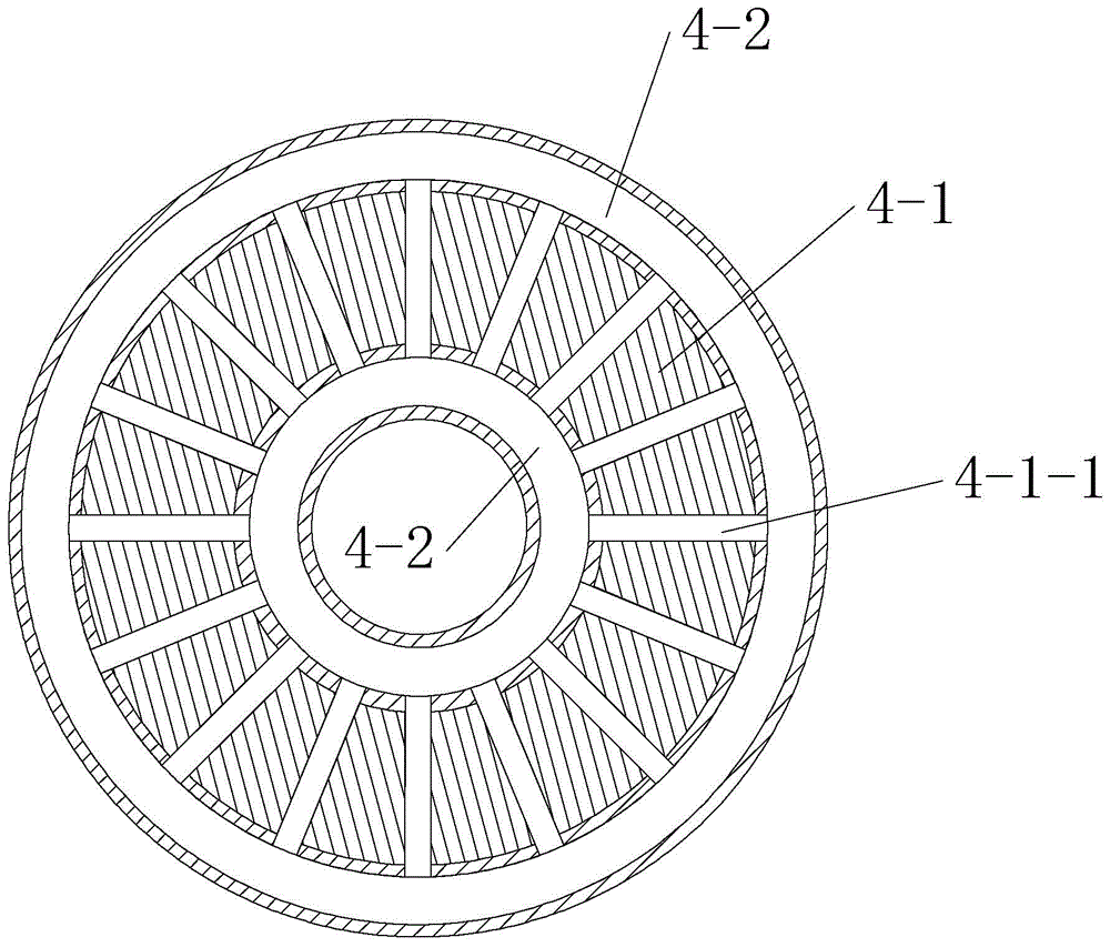
[0056] Specific implementation mode two: see image 3 Describe this embodiment, the difference between this embodiment and the direct-drive permanent magnet wind heating system described in Embodiment 1 is that the stator unit 4 consists of a reaction plate 4-1 and two heat medium pipelines 4-2 constitute,
[0057] The reaction plate 4-1 is a disc-shaped structure, and the center of the reaction plate 4-1 is provided with a through hole,
[0058] The heat medium pipeline 4-2 is circular,
[0059] On the reaction plate 4-1, there are multiple heat transfer holes 4-1-1 along the radial direction, and the multiple heat transfer holes 4-1-1 are evenly arranged along the circumferential direction of the reaction plate 4-1.
[0060] A heat medium pipeline 4-2 is respectively provided on the outer circumference side and the inner circumference side of the reaction plate 4-1, and the two heat medium pipelines 4-2 are connected through the heat medium transmission hole 4-1-1.
[006...
specific Embodiment approach 3
[0062] Specific implementation mode three: see Figure 4 and Figure 5 Describe this embodiment. The difference between this embodiment and the direct-drive permanent magnet wind heating system described in Embodiment 1 is that each rotor unit 3 is composed of a plurality of permanent magnets 3-1 and a magnetically conductive yoke plate 3 -2 structure, the magnetic yoke plate 3-2 is a disc-shaped structure, the magnetic yoke plate 3-2 is sleeved on the rotor shaft,
[0063]The permanent magnet 3-1 is a flat plate structure, and a plurality of permanent magnets 3-1 are fixed on the air gap side surface of the magnetic yoke plate 3-2, and are evenly arranged along the circumferential direction of the magnetic yoke plate 3-2. The magnetization direction of the magnet 3-1 is radial magnetization, and the magnetization directions of the two adjacent permanent magnets 3-1 on each magnetic yoke plate 3-2 are opposite,
[0064] The number of permanent magnets 3-1 on the air gap side...
PUM
 Abstract
Description
Claims
Application Information
 - R&D Engineer
- R&D Manager
- IP Professional
- Industry Leading Data Capabilities
- Powerful AI technology
- Patent DNA Extraction
Browse by: Latest US Patents, China's latest patents, Technical Efficacy Thesaurus, Application Domain, Technology Topic, Popular Technical Reports.
© 2024 PatSnap. All rights reserved.Legal|Privacy policy|Modern Slavery Act Transparency Statement|Sitemap|About US| Contact US: help@patsnap.com


