Single-face bonding method suitable for hard alloy strips in hard alloy hard-face machining process and application

A cemented carbide and alloy strip technology, which is applied in metal processing equipment, manufacturing tools, connecting components, etc., can solve the problems of low efficiency, high cost, and inability to guarantee the accuracy of cemented carbide strip bonding, so as to ensure the bonding. Quality, easy operation, guarantee the effect of good quality

Active Publication Date: 2015-10-14
株洲金韦硬质合金有限公司
View PDF5 Cites 7 Cited by
  • Summary
  • Abstract
  • Description
  • Claims
  • Application Information

AI Technical Summary

Problems solved by technology

[0007] The technical problem to be solved in the present invention is to provide a bonding method suitable for cemented carbide strips in the processing of cemented carbide hard surfaces for the defects of low efficiency, high cost and unguaranteed precision in the bonding of existing cemented carbide strips , the method is simple, efficient, and highly accurate, and effectively solves the technical defect of manually placing and pasting cemented carbide strips to complete cemented carbide hard surface processing

Method used


Image

  • Single-face bonding method suitable for hard alloy strips in hard alloy hard-face machining process and application
  • Single-face bonding method suitable for hard alloy strips in hard alloy hard-face machining process and application
  • Single-face bonding method suitable for hard alloy strips in hard alloy hard-face machining process and application

Examples


Embodiment 1

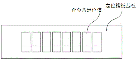
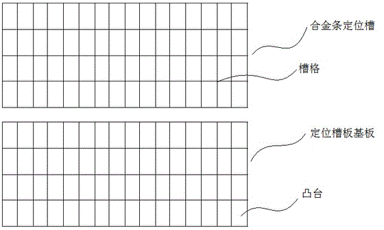
[0053] This embodiment provides a positioning groove plate suitable for bonding cemented carbide strips in cemented carbide hard surface processing, and its structural schematic diagram is shown in the attached figure 1 shown. The positioning slot plate includes a base plate and an alloy bar positioning slot arranged on the base plate, and the size of the alloy bar positioning slot matches the size of the cemented carbide bar.

[0054] The base plate of the positioning groove plate and the positioning groove are an integrated structure, and the depth of the alloy strip positioning groove on the substrate is not greater than the thickness of the hard alloy strip. After placing an appropriate amount of hard alloy strips on the positioning groove plate, most of the hard alloy strips fall into the positioning grooves one by one, and the individual positioning grooves that do not fall into the hard alloy strips can be placed manually. The cemented carbide strips are swept off the ...

Embodiment 2

[0057] Based on the positioning groove plate described in Embodiment 1, this embodiment provides a bonding method suitable for cemented carbide strips in the processing of cemented carbide hard surfaces. The schematic diagram of the process flow is shown in the attached Figure 4 shown. The method comprises the steps of:

[0058] S1. Prepare the positioning groove plate;

[0059] S2. Put the hard alloy strip on the positioning slot plate, place the hard alloy strip on the positioning slot plate as required, and drop the excess hard alloy strip from the positioning slot plate;

[0060] S3. Bond the cemented carbide strip with a perforated adhesive tape, so that the cemented carbide strip and one side of the tape are firmly bonded; this embodiment uses a single-sided tape (only one side of the tape uses glue-based materials), so that the tape has glue One side is firmly bonded to the carbide strip;

[0061] S4. Fix the hard alloy strip or block by spot welding;

[0062] Wher...

Embodiment 3

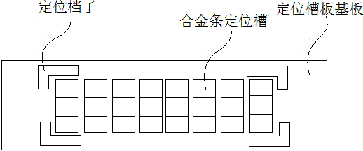
[0073] This embodiment provides another positioning groove plate suitable for bonding cemented carbide strips in cemented carbide hard surface processing, and its structural schematic diagram is shown in the attached image 3 shown. The positioning slot plate includes a base plate and an alloy bar positioning slot arranged on the base plate, and the size of the alloy bar positioning slot matches the size of the cemented carbide bar.

[0074] The positioning slot plate includes a base plate and an alloy bar positioning slot arranged on the base plate. The base plate is composed of several liftable bosses, and the alloy bar positioning slot is a grid composed of several hollowed out slots. Only one tungsten carbide strip can be accommodated in the center; the boss can rise or fall from the corresponding slot hole position; the size of the boss and the slot match and match the size of the tungsten carbide strip . First, make the boss in the initial state, and the plane formed b...


PUM


Abstract

The invention provides a single-face bonding method suitable for hard alloy strips in a hard alloy hard-face machining process and application. A locating groove plate for bonding is scientifically designed, the hard alloy strips are placed on the locating groove plate, the hard alloy strips are bonded through punched single-face adhesive tape, and the hard alloy strips or blocks are fixed through spot welding; and then the adhesive tape is placed on a steel surface of a to-be-machined component, and through spray welding, bead weld and grinding, the steel surface is machined into a hard surface. According to the method, the aim that a large number of hard alloy strips are bonded at a time is simply and easily achieved, the bonding efficiency is greatly improved, and the conditions that due to manual operation, the bonding angles are different, and the bonding intervals are uneven are avoided; the bonding precision is improved, and wear resistance of the product hard surface can be effectively ensured and improved; and the method can be well applied to the aspect of hard-face machining of centering guides or TC bearings of drilling tools or screw drilling tools.

Description

technical field [0001] The present invention relates to the technical field of cemented carbide material manufacturing, more specifically, relates to a method for bonding a large amount of small-sized cemented carbide and its application to the bonding of alloy blocks on the surface of centralizers or TC radial bearings for screw drilling tools Applications. Background technique [0002] Exploitation drilling tool or screw drilling tool is a volumetric downhole dynamic drilling tool that uses drilling fluid as power and converts fluid pressure energy into mechanical energy. It plays an important role in the drilling field. [0003] Centralizers and TC bearings (radial bearings) are important parts of drilling tools, such as TC bearings, which bear the lateral force generated by the rotation of the drill bit and cardan shaft in the screw drilling tool. The key component of the service life of the tool. [0004] The surfaces of the centralizer and the TC bearing need to be w...

Claims


Application Information

Patent Timeline
Patent Type & Authority Applications(China)
IPC IPC(8): F16B11/00B23K31/02
CPCB23K31/02F16B11/00
Inventor 汪文斋刘能文杨宇向勇
Owner 株洲金韦硬质合金有限公司
Why Eureka
Try Eureka