
Multiple-input-multiple-output visible light MIMO system

A multi-output, visible light technology, applied in short-range systems, free space transmission, etc., can solve the problems of lack of frequency and phase information, LED sub-channel interference, indistinguishability, etc., to improve spatial multiplexing efficiency and reduce correlation. Effect

Inactive Publication Date: 2015-10-14
TSINGHUA UNIV +2
View PDF3 Cites 37 Cited by
  • Summary
  • Abstract
  • Description
  • Claims
  • Application Information

AI Technical Summary

Problems solved by technology

However, since visible light communication uses intensity modulation and direct detection, and lacks frequency and phase information, the interference between different LED sub-channels is serious and there is a strong correlation. It is difficult to decompose the information of each sub-channel, resulting in the inability to obtain spatial complex Use gain
[0005] In the related art, in the imaging MIMO system, the receiver is composed of multiple picture elements, and the optical signals sent by LEDs in different directions are projected onto different picture elements to eliminate the interference between each sub-channel, but the imaging MIMO It is sensitive to the position of the LED, and the change of the position can cause the light signals from different LEDs to be projected on the same pixel, resulting in indistinguishability, which limits its application in mobile scenes, so it needs to be improved

Method used


Image

  • Multiple-input-multiple-output visible light MIMO system
  • Multiple-input-multiple-output visible light MIMO system
  • Multiple-input-multiple-output visible light MIMO system

Examples


Embodiment Construction

[0026] Embodiments of the present invention are described in detail below, examples of which are shown in the drawings, wherein the same or similar reference numerals designate the same or similar elements or elements having the same or similar functions throughout. The embodiments described below by referring to the figures are exemplary and are intended to explain the present invention and should not be construed as limiting the present invention.

[0027] In addition, the terms "first" and "second" are used for descriptive purposes only, and cannot be interpreted as indicating or implying relative importance or implicitly specifying the quantity of indicated technical features. Thus, a feature defined as "first" and "second" may explicitly or implicitly include one or more of these features. In the description of the present invention, "plurality" means two or more, unless otherwise specifically defined.

[0028] In the present invention, unless otherwise clearly specified...


PUM


Abstract

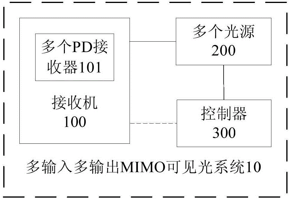
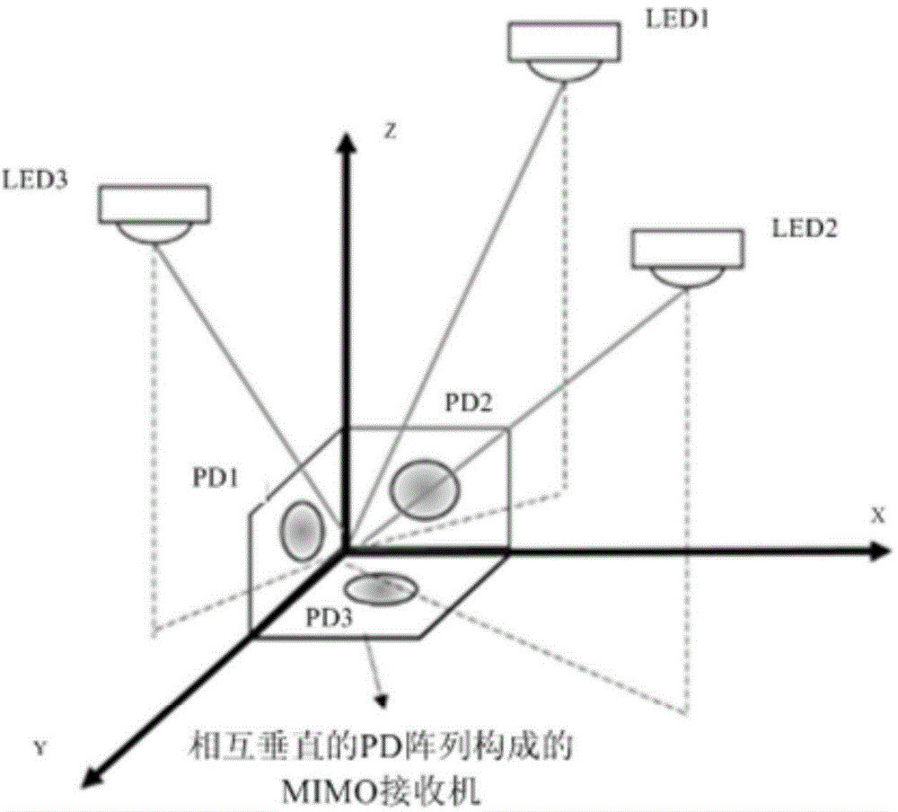
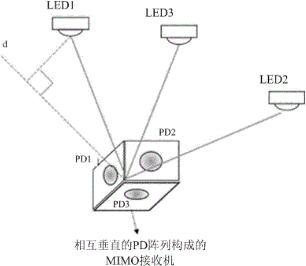
The invention discloses a multiple-input-multiple-output visible light MIMO system comprising a receiver which comprises multiple PD receptors; multiple light sources which are arranged at different positions, wherein the connecting lines between any two light sources of the multiple light sources and the receiver are not in the same straight line; and a controller which independently controls each light source to emit light signals in different power in a training phase respectively so that a gain matrix is obtained according to light intensity of each light source received by the receiver, multiple light sources are controlled to emit the light signals simultaneously in a communication phase, emitting power of each light source is obtained according to the gain matrix and light intensity received by the receiver at the time, and thus the light signals emitted by different light sources can be distinguished. According to the system of the embodiment, correlation among all sub-channels can be effectively reduced, spatial multiplexing efficiency can be enhanced and spatial multiplexing gain can be acquired.

Description

technical field [0001] The invention relates to the technical field of wireless communication, in particular to a multiple-input multiple-output visible light MIMO system. Background technique [0002] Visible light communication technology is a wireless communication technology that uses the visible light band as an optical carrier for communication, and can realize high-speed data transmission. Compared with traditional wireless communication technology, visible light communication technology has the characteristics of high efficiency, no electromagnetic interference, and environmental protection. [0003] Specifically, the visible light communication technology is to transmit information through the driving circuit, high-speed modulation to the LED optical signal, and the receiving end uses a photoelectric converter such as a photodiode (PD) to convert the optical signal into an electrical signal, and demodulates effective information. Realize the communication function....

Claims


Application Information

Patent Timeline
IPC IPC(8): H04B10/116
Inventor 魏凌张洪明宋健郎凯
Owner TSINGHUA UNIV
Learn More