Light source system and projection system

一种光源系统、光源的技术,应用在光学显示领域,能够解决光源系统亮度低、“彩虹”效应影响等问题,达到保证亮度、结构简单、成本低的效果

Active Publication Date: 2015-10-14
APPOTRONICS CORP LTD
View PDF6 Cites 33 Cited by
  • Summary
  • Abstract
  • Description
  • Claims
  • Application Information

AI Technical Summary

Problems solved by technology

[0005] The purpose of the present invention is to provide a light source system and a projection system, aiming to solve the problems of low brightness of the light source system and the influence of the "rainbow" effect in the prior art

Method used


Image

  • Light source system and projection system
  • Light source system and projection system
  • Light source system and projection system

Examples


Embodiment Construction

[0044] In order to make the object, technical solution and advantages of the present invention clearer, the present invention will be further described in detail below in conjunction with the accompanying drawings and embodiments.

[0045] The three primary color lights described in the present invention are red, green and blue three-color lights. One cycle mentioned in the present invention refers to the processing time of one frame of data.

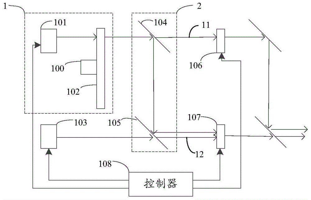
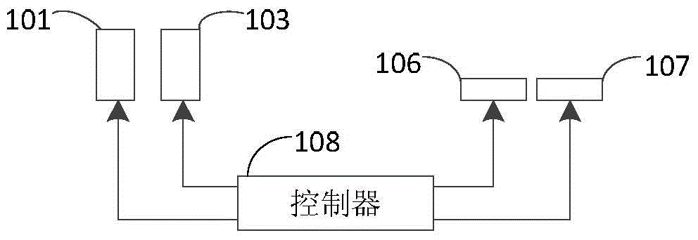
[0046] The present invention proposes the first embodiment about the light source system, which is combined below Figure 1 to Figure 7 Be explained. figure 1It is a schematic structural diagram of the light source system in the first embodiment of the present invention, the light source system: a first light source 1, a second light source 103, a light splitting and combining device 2, a first spatial light modulator 106, and a second spatial light modulator 107 and controller 108 . Wherein the first light source 1 and the second li...


PUM


Abstract

A light source system and projection system, the light source system comprising: a first light source (1) producing first wide spectrum light, a second light source (103) producing second wavelength light, a light splitting and light combining device (2) used to split and combine light, a first spatial light modulator (106), a second spatial light modulator (107), and a controller (108) controlling the first light source (1) and the second light source (103) and modulating the first spatial light modulator (106) and the second spatial light modulator (107). The projection system comprises the light source system. The light source system and projection system have high brightness and wide color gamut, effectively eliminating rainbow effect, and also have a simple structure and low cost.

Description

technical field [0001] The invention relates to the field of optical display, more specifically, to a light source system and a projection system. Background technique [0002] With the maturity of projection display technology, the market has gradually developed from the original single-chip DMD projection technology to three-chip DMD projection display system. [0003] In the traditional single-chip DMD projection technology, the light source adopts white light source. After the white light source passes through the spectral filter, the three primary colors of red, green, and blue are sequentially generated, and the three primary colors of red, green, and blue reach the DMD in sequence. Exit after DMD treatment. Although this single-chip DMD projection system has a simple structure, the utilization rate of the light source is very low, and most of the light is lost after passing through the spectral filter, which leads to low brightness of the projection system. Moreover...

Claims


Application Information

Patent Timeline
Patent Type & Authority Applications(China)
IPC IPC(8): H04N9/31G02B27/10F21V9/40
CPCH04N9/3158H04N9/3164G03B21/2013G03B33/12G03B21/005H04N9/3111G03B33/14G03B33/08H04N9/3114G02B26/008G02B27/141G03B21/204G03B21/208H04N9/3155H04N9/3161
Inventor 李屹叶红王则钦
Owner APPOTRONICS CORP LTD
Why Eureka
Try Eureka