
Method for conducting line-by-line milling on rotor tooth profile surface of large screw compressor along spiral line

A screw compressor and helix technology, which is applied in the field of row-by-row milling of the tooth profile surface of a large screw compressor rotor along the helix, can solve the problems of high cost and difficult processing of large screw rotors, and achieves high processing accuracy and good popularization and application. Value, the effect of low production cost

Active Publication Date: 2015-10-21
XIAMEN UNIV +1
View PDF6 Cites 6 Cited by
  • Summary
  • Abstract
  • Description
  • Claims
  • Application Information

AI Technical Summary

Problems solved by technology

[0004] The purpose of the present invention is to solve the problem that the existing large-scale screw rotors are difficult to process, and to provide a method for milling the tooth profiles of large-scale screw rotors line by line along the helical line. Milling large screw rotors line by line on the screw rotor milling machine avoids the high-cost investment required by increasing the size of the machine tool and the size of the milling cutter, and can realize CNC milling of large screw rotor tooth profiles on existing small-sized machine tools

Method used


Image

  • Method for conducting line-by-line milling on rotor tooth profile surface of large screw compressor along spiral line
  • Method for conducting line-by-line milling on rotor tooth profile surface of large screw compressor along spiral line
  • Method for conducting line-by-line milling on rotor tooth profile surface of large screw compressor along spiral line

Examples


Embodiment Construction

[0018] The present invention will be described in detail below in conjunction with the accompanying drawings and specific embodiments.

[0019] A row-by-row milling method along a helical line of a large screw compressor rotor, the specific steps are as follows:

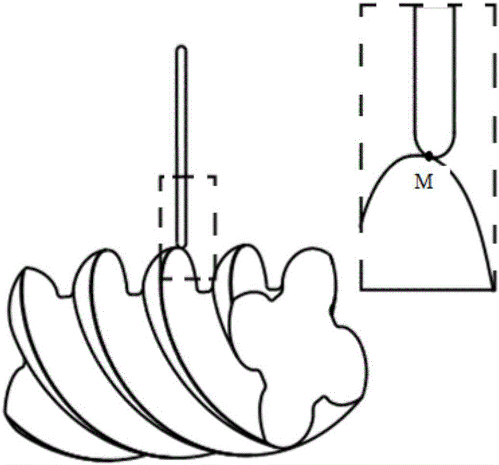
[0020] The first step is to select the disc-shaped arc milling cutter. The arc radius of the disc-shaped arc milling cutter is r, and the selection of r should ensure that it is smaller than the normal tooth profile curvature radius of the helical surface, and take the larger value as possible .

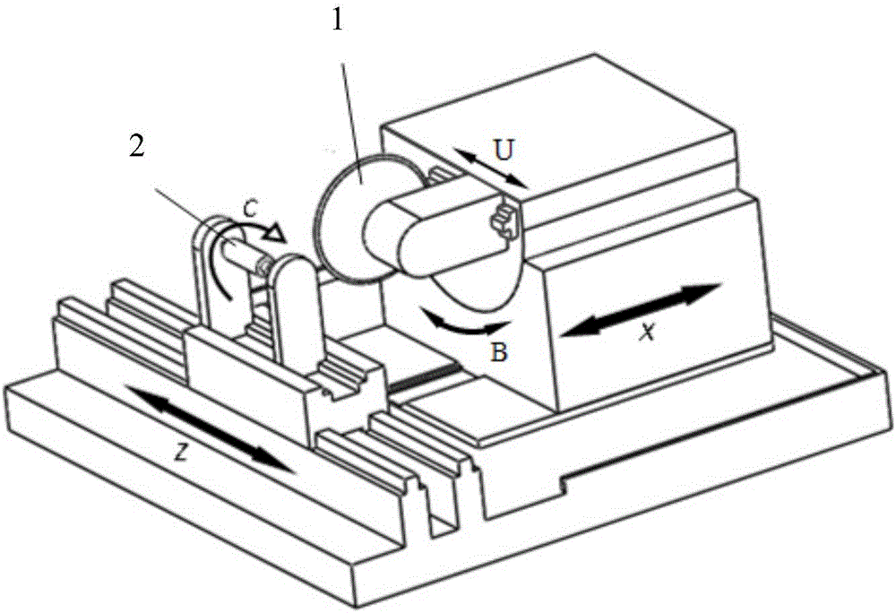
[0021] The second step is to determine the contact point between the disc arc milling cutter and the workpiece to be processed. The disk arc milling cutter 1 that the first step is trimmed is installed on the screw rotor 2 milling machine (such as figure 1 , where the X-axis is the feed axis of the milling cutter, the B-axis is the swing axis of the milling cutter, the U-axis is the micro-feeding axis of the milling cutte...


PUM


Abstract

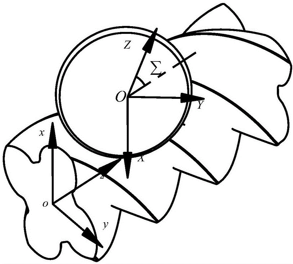
The invention provides a method for conducting line-by-line milling on a rotor tooth profile surface of a large screw compressor along a spiral line and relates to screw compressors. The method comprises the steps that firstly, a disk-type arc milling cutter is selected, and the arc radius r of the disk-type arc milling cutter is determined; secondly, rotor profile line value points are selected according to the initial line-by-line step lengths of the spiral line; thirdly, the envelope path of the disk-type arc milling cutter for machining the rotor profile is calculated according to the spiral surface forming principle, and an initial position point of the envelope path is determined; fourthly, a spiral groove is machined line by line along the spiral line; fifthly, other spiral grooves are machined in sequence until all the spiral grooves are formed. Only the existing common disk-type arc milling cutter and a numerically-controlled screw rotor milling machine are needed; the relative machining positions of the milling cutter and the screw rotor are deduced by establishing a segmented milling mathematic model; the disk-type arc milling cutter can be mounted on the numerically-controlled screw rotor milling machine to conduct line-by-line milling on the large screw rotor through the existing numerical control technology. The method has the advantages that precision is high, cost is low, and the existing small machine tool can be used for conducting numerical control milling on the large screw rotor.

Description

technical field [0001] The invention relates to a screw compressor, in particular to a method for milling a rotor tooth profile surface of a large screw compressor line by line along a helical line. Background technique [0002] Due to the characteristics of stable high-speed operation, multi-phase mixed transmission, displacement almost unaffected by exhaust pressure and easy operation and maintenance, screw compressors have been widely used in machinery, chemical industry, metallurgy, construction, mining and aerospace in recent years. In the industrial fields such as , the processing of the screw rotor as its core component has received extensive attention. [0003] Form milling is a milling process method commonly used in screw rotor tooth slots. However, there are many problems to be solved in the process of milling with forming milling cutters. With the development of machinery manufacturing industry, screw compressors, which are widely used in mining, construction, a...

Claims


Application Information

Patent Timeline
IPC IPC(8): B23C3/32
CPCB23C3/32
Inventor 姚斌卢杰罗琪周斌向明新唐峰博
Owner XIAMEN UNIV
Learn More