Laser synchronous welding device

A welding equipment and laser technology, which is applied in the field of laser synchronous welding equipment, achieves the effects of fast speed, short welding time and wide application range

Active Publication Date: 2015-10-21
SHANGHAI SEEYAO ELECTRONICS CO LTD
View PDF5 Cites 12 Cited by
  • Summary
  • Abstract
  • Description
  • Claims
  • Application Information

AI Technical Summary

Problems solved by technology

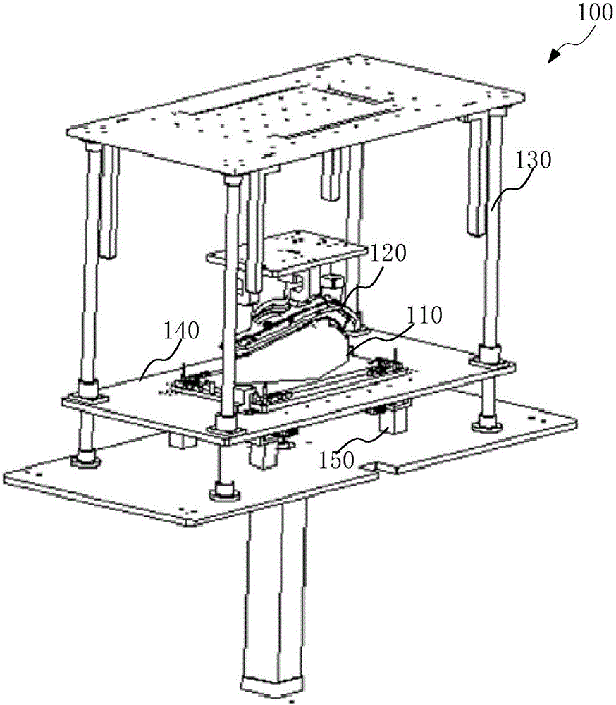
[0007] In view of the above-mentioned shortcomings of the prior art, the object of the present invention is to provide a laser synchronous welding equipment, which is used to solve the problem in the prior art that simultaneous welding of complex curved surface lamps cannot be completed at the same time

Method used


Image

  • Laser synchronous welding device
  • Laser synchronous welding device
  • Laser synchronous welding device

Examples


Embodiment Construction

[0041] The implementation of the present invention will be illustrated by specific specific examples below, and those skilled in the art can easily understand other advantages and effects of the present invention from the contents disclosed in this specification.

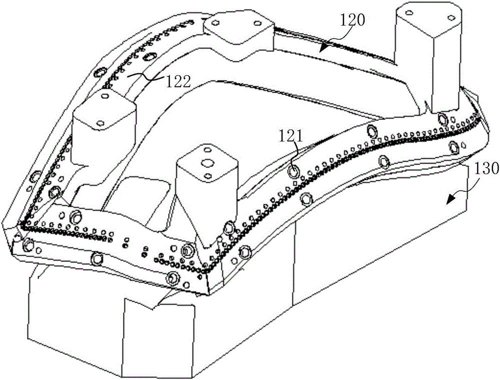
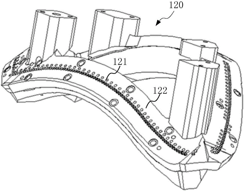
[0042] see Figure 1 to Figure 4 . It should be noted that the structures, proportions, sizes, etc. shown in the drawings attached to this specification are only used to match the content disclosed in the specification, for those who are familiar with this technology to understand and read, and are not used to limit the implementation of the present invention. Limiting conditions, so there is no technical substantive meaning, any modification of structure, change of proportional relationship or adjustment of size, without affecting the effect and purpose of the present invention, should still fall within the scope of the present invention. within the scope covered by the disclosed technical content. At the same ti...


PUM


Abstract

The invention provides a laser synchronous welding device which is used for welding an automobile lamp body and a lens. The laser synchronous welding device comprises a laser emitter, a first mold, a second mold and a light guiding pipe. The laser emitter is connected with an optical fiber set and meanwhile provides a plurality of beams of lasers. The first mold is used for containing the lamp body and suitable for moving up and down relative to the second mold. The second mold is used for containing the lens and evenly provided with a plurality of optical fiber fixing holes at the position corresponding to the welding position of the lens. Each optical fiber of the optical fiber set is connected to the corresponding optical fiber fixing hole. The light guiding pipe is used for shaping and focusing the lasers and located in the second mold. The light guiding pipe transversely penetrates the optical fiber fixing holes, and therefore the lasers can irradiate the light guiding pipe after being transmitted through the optical fibers. When the first mold moves to coincide with the second mold, the lasers shaped by the light guiding pipe penetrate the lens and are focused on welding ribs of the lamp body. The welding ribs of the lamp body are molten, and therefore the lamp body and the lens can be welded together. The device finishes welding the whole automobile lamp synchronously at a time and is high in efficiency and low in cost.

Description

technical field [0001] The invention relates to the technical field of manufacturing automobile lamps, in particular to a laser synchronous welding equipment for welding lamp bodies and light distribution mirrors of automobile lamps. Background technique [0002] At present, friction welding and hot plate welding are generally used for welding automobile lights: [0003] Friction welding is that during welding, the rotating workpiece starts to rotate at a high speed under the drive of the motor, and the moving workpiece gradually moves closer to the rotating workpiece under the action of axial force. After the workpieces on both sides are contacted and pressed tightly, some asperities on the friction interface first stick Contact and shear, and generate frictional heat. As the actual contact area increases, the friction torque rises rapidly, and the temperature at the friction interface rises accordingly, and the friction interface is gradually covered by a layer of high-te...

Claims


Application Information

Patent Timeline
Patent Type & Authority Applications(China)
IPC IPC(8): B23K26/21
CPCB23K26/20B29C65/1635B29C65/1667B29C65/1687B29C65/7841B29C66/112B29C66/131B29C66/301B29C66/542B29C66/8242B29C66/8322B29C66/9161B29C66/9241B29L2031/747
Inventor 郭肇基杨晓锋黄海王永和
Owner SHANGHAI SEEYAO ELECTRONICS CO LTD
Why Eureka
Try Eureka