Complex surface on-machine test method of five-axis machining center

A five-axis machining center, complex profile technology, used in metal processing machinery parts, metal processing equipment, manufacturing tools, etc., can solve the impact, such as lighting conditions, surface state reflection conditions, shadows, light blocking, errors, etc. , to reduce the scrap rate of workpieces, improve production efficiency, and reduce time costs

Active Publication Date: 2015-10-21
TIANJIN UNIV
View PDF11 Cites 11 Cited by
  • Summary
  • Abstract
  • Description
  • Claims
  • Application Information

AI Technical Summary

Problems solved by technology

However, the radiation characteristics of the object also have a great influence on the laser measurement results, such as lighting

Method used


Image

  • Complex surface on-machine test method of five-axis machining center
  • Complex surface on-machine test method of five-axis machining center
  • Complex surface on-machine test method of five-axis machining center

Examples


Embodiment 1

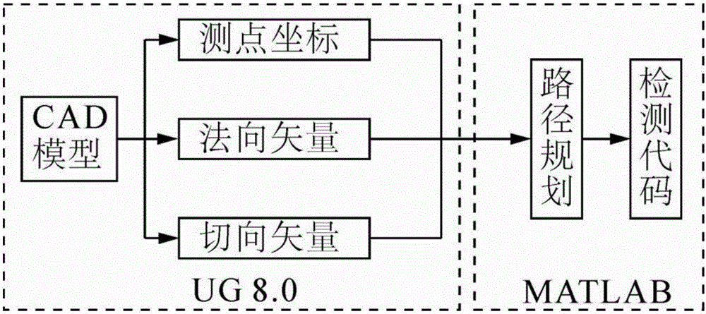
[0034] A method for on-machine detection of complex profiles of a five-axis machining center, see figure 1 , the method for on-machine detection of complex profiles includes the following steps:

[0035] 101: Based on the solid modeling technology of the commercial software UG NX8.0, plan the detection points, and obtain the coordinates, normal vectors and tangential vectors of the surface detection points;

[0036] 102: Use commercial visual mathematics software to read the coordinates, normal vector and tangential vector of the detection point, and plan the detection path;

[0037] 103: Detect the surface through the detection path, and generate the corresponding on-machine detection code according to the type of the five-axis machining center.

[0038] Wherein, in step 101, based on the solid modeling technology of the commercial software UG NX8.0, the detection points are planned, and the steps of obtaining the coordinates, normal vectors and tangential vectors of the sur...

Embodiment 2

[0046] This embodiment describes in detail the scheme in Embodiment 1 in conjunction with specific calculation formulas, examples, tests and accompanying drawings, see the following description for details:

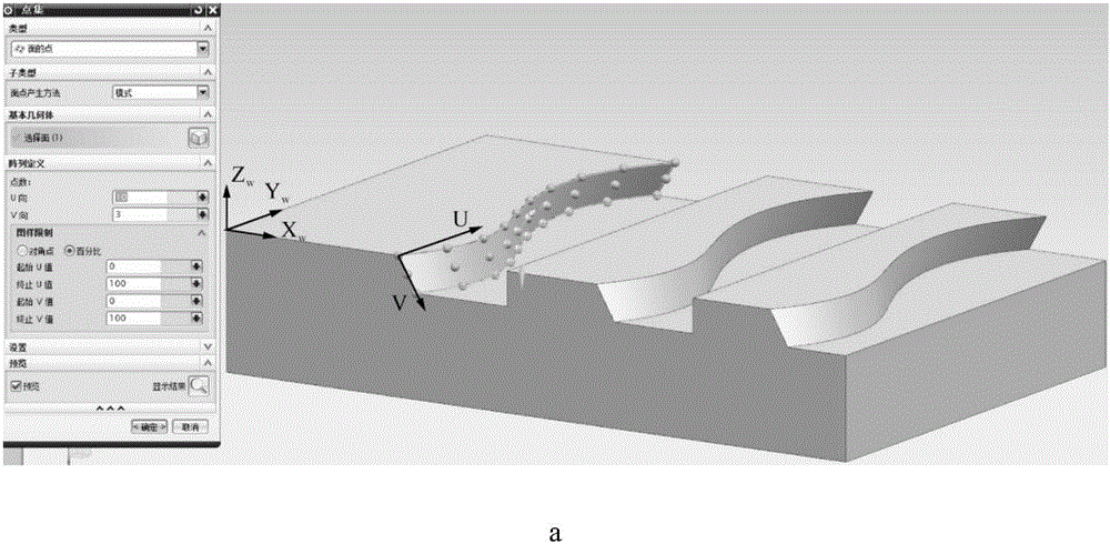
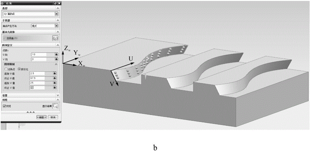
[0047] 201: Based on the solid modeling technology of the commercial software UG NX8.0, plan the detection points, obtain the coordinates, normal vectors and tangential vectors of the surface detection points, and save them in the form of TXT files;

[0048] Wherein, the present invention is based on the point set function of commercial software UG NX8.0, in workpiece coordinate system (X w , Y w ,Z w ), select the detection surface, set the number of detection points according to the direction of the wire and the busbar of the NURBS (Non-Uniform Rational B-spline) surface, that is, the u and v directions, and create a group of detection points corresponding to the detection surface, such as figure 2As shown in a (including 10 columns, each column has 3 detection point...


PUM


Abstract

The invention discloses a complex surface on-machine test method of a five-axis machining center. The complex surface on-machine test method includes the following steps that the detection point is planned through a solid modeling technology based on commercial software UG NX8.0, and the coordinates, the normal vector and the tangential vector of the surface detection point are obtained; the coordinates, the normal vector and the tangential vector of the detection point are read through commercial visual digital software, and the detection path is planned; the surface is detected through the detection path, and a corresponding on-machine detection code is generated according to the type of the five-axis machining center. By means of the method, when a workpiece is machined, the workpiece does not need to be conveyed to a detection device from a machine tool, and the quality of the workpiece can be detected at any time in the machining process; meanwhile, by means of obtained results, positioning and machining correction of the workpiece are guided, production efficiency of the machining process is improved, occurring errors are detected in real time as early as possible at low time cost, and the scrap rate of the workpiece is reduced.

Description

technical field [0001] The invention relates to the technical field of numerical control machining, in particular to a method for on-machine detection of complex profiles of a five-axis machining center. Background technique [0002] In aerospace, automobiles, ships and various high-tech equipment, parts with complex spatial surface geometry are increasingly widely used, and play an important role in achieving physical performance requirements such as system mechanical properties, optical properties, and fluid properties. The requirements for machining accuracy and quality inspection accuracy of CNC machine tools are also increasing day by day. With the development of modern manufacturing inspection technology, a new measurement concept has been proposed, and its derived detection methods can be mainly divided into two types: offline detection and online detection. As a typical representative of off-line measurement, three-coordinate measuring machines are widely used in in...

Claims


Application Information

Patent Timeline
IPC IPC(8): B23Q17/20
CPCB23Q17/20
Inventor 何改云马文魁丁伯慧黄鑫
Owner TIANJIN UNIV
Why Eureka
Try Eureka