Multi-rotor craft emergency protection system and method

A multi-rotor aircraft and emergency protection technology, applied in emergency equipment, aircraft parts, parachutes, etc., can solve the problems of inability to achieve continuous power-off operation, high working temperature, and easy damage to equipment, so as to reduce crashes and accidental injuries to surrounding areas. The effect of the probability of the object, the small load capacity, and the high safety

Active Publication Date: 2015-10-21
XIHUA UNIV
View PDF16 Cites 8 Cited by
  • Summary
  • Abstract
  • Description
  • Claims
  • Application Information

AI Technical Summary

Problems solved by technology

The disadvantages of this patent are: without the ground control remote control, the application and the electric flight equipment in the air cannot realize coherent operations such as power-off and parachute ejection, and lack of more accurate landing; damaged, and subsequent refilling with mixture and high-pressure gas is difficult to achieve

Method used


Image

  • Multi-rotor craft emergency protection system and method
  • Multi-rotor craft emergency protection system and method
  • Multi-rotor craft emergency protection system and method

Examples


Embodiment 1

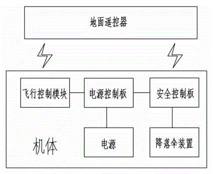
[0044] An emergency protection system for a multi-rotor aircraft, including:

[0045] Parachute device used to prevent the body from falling;

[0046] The safety control panel used to control the opening of the parachute device;

[0047] Power control board used to control power off;

[0048] Ground remote control used to control the safety control board and flight control module;

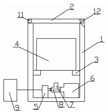
[0049] The parachute device, the safety control board 9, and the power control board are all installed on the body. The parachute device and the power control board are connected to the safety control board 9 respectively. The safety control board 9 and the flight control module are respectively connected to the safety control board 9 through 2.4G wireless The data transmission communicates with the ground remote controller; the parachute device includes a parachute 4 and a jet device, the jet device is equipped with high-pressure gas, the jet port of the jet device is located under the parachute 4, the saf...

Embodiment 2

[0062] An emergency protection system for a multi-rotor aircraft, including:

[0063] Parachute device used to prevent the body from falling;

[0064] The safety control panel used to control the opening of the parachute device;

[0065] Power control board used to control power off;

[0066] Ground remote control used to control the safety control board and flight control module;

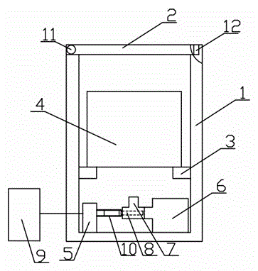
[0067] The parachute device, the safety control board 9, and the power control board are all installed on the airframe, and the parachute device and the power control board are respectively connected to the safety control board 9. The safety control board 9 and the flight control module are respectively connected through 5.8G wireless The digital communication network communicates with the ground remote controller; the parachute device includes a parachute 4 and a jet device, the jet device is equipped with high-pressure gas, the jet port of the jet device is located under the parachute 4, and the safety co...


PUM


Abstract

The invention discloses a multi-rotor craft emergency protection system. The system comprises a parachute device, a safety control board, a power control board and a ground remote control unit. The parachute device, the safety control board and the power control board are all installed on a craft body. The parachute device and the power control board are both connected with the safety control board. The safety control board and a flight control module are in communication with the ground remote control unit in a wireless manner. The parachute device comprises a parachute and a jet device. The jet device contains high-pressure gas. A jet exhaust of the jet device is located below the parachute. The safety control board is connected with the jet device and controls the high-pressure gas jetted from the jet device to blow the parachute out. Emergency protection measures are additionally arranged on an existing multi-rotor craft, an air crash accident is effectively avoided, safety is high, the probability of self-crash and mistaken surrounding object damage of the craft can be reduced, and the overall safety and reliability are improved.

Description

Technical field [0001] The invention relates to the field of multi-rotor aircraft, and more specifically, to an emergency protection system for multi-rotor aircraft and an emergency protection method for the emergency protection system. Background technique [0002] Multi-rotor aircraft is a new type of unmanned aerial vehicle that has developed rapidly in recent years. It has the characteristics of small size, light weight, and low price. It can carry a certain weight of equipment to complete disaster monitoring, terrain detection, radio monitoring and forest fire cruise warning. But in practical applications, there are often operating errors and hardware and software failures. [0003] The structure of the existing multi-rotor aircraft includes an aircraft body, a flight control module, a navigation module, a motor and a power supply. The flight control module, navigation module, motor and power supply are all installed on the body. The flight control module is connected to the n...

Claims


Application Information

Patent Timeline
Patent Type & Authority Applications(China)
IPC IPC(8): B64D17/72
Inventor 孔明明裴峥夏爽刘晶
Owner XIHUA UNIV
Why Eureka
Try Eureka