

Full-floating bearing turbocharger rotor system
A technology of turbocharger and turbine rotor, which is applied to sliding contact bearings, rotating bearings, bearings, etc., can solve the problems of limiting the reliability and structural size of turbochargers, complex bearing systems, and too many parts and so on. , to achieve the effect of improving the competitive advantage, simplifying the machining process and simplifying the assembly process
- Summary
- Abstract
- Description
- Claims
- Application Information
AI Technical Summary
Problems solved by technology
Method used
Image

Examples
Embodiment Construction
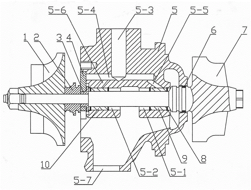
[0048] A fully floating bearing turbocharger rotor system, comprising an impeller 1, a sealing ring 6, a bearing body 11, a turbine end full floating bearing 12, a compressor end full floating bearing 13, a compressor end sealing sleeve 14 and a turbine rotor shaft 15.
[0049] The bearing body 11 is provided with a first shaft hole 11-1 and a second shaft hole 11-2, and one end of the first shaft hole 11-1 is provided with a turbine end full floating bearing installation hole 11-1- 1. The port of the full floating bearing installation hole 11-1-1 at the turbine end is provided with a first oil row chamfer 11-1-2, and one end of the second shaft hole 11-2 is provided with
[0050] The full floating bearing mounting hole 11-2-1 at the compressor end is provided with a second oil row chamfer 11-2-2 at the port of the full floating bearing mounting hole 11-2-1 at the compressor end.
[0051] A threaded hole 11-6 for mounting the back plate is provided on the end face of the compr...
PUM
 Abstract
Description
Claims
Application Information