Voltage and power balance control method for modular power electric transformer

A technology of power electronics and power balance, which is applied in the direction of adjusting electric variables, control/regulation systems, output power conversion devices, etc., can solve the problems of improving power quality, large volume and weight, voltage and power imbalance, etc., to reduce current Sensor and sampling link, realize the balance of voltage and power, realize the effect of power and voltage balance

Inactive Publication Date: 2015-10-21
XIANGTAN UNIV
View PDF4 Cites 25 Cited by
  • Summary
  • Abstract
  • Description
  • Claims
  • Application Information

AI Technical Summary

Problems solved by technology

However, its main function is to realize the basic voltage level conversion and electrical isolation. The function is relatively single, and there are a series of disadvantages: large volume and weight; insulating oil poses a threat to the environment; it cannot maintain output voltage stability and improve power quality.
[0004] At present, limited by the withstand voltage level of power semiconductor devices, single-stage power electronic transformers cannot meet the voltage level of the distribution network. This is a major factor that limits the practical application of power electronic transformers. Make up for the lack of single-stage type, but the series-parallel connection of modules will introduce the imbalance of voltage and power between modules, and even cause the entire power electronic transformer system to fail to work normally, so corresponding control methods must be adopted to ensure power and power. voltage balance

Method used


Image

  • Voltage and power balance control method for modular power electric transformer
  • Voltage and power balance control method for modular power electric transformer
  • Voltage and power balance control method for modular power electric transformer

Examples


Embodiment Construction

[0017] The present invention will be described in detail below in conjunction with the accompanying drawings and specific embodiments.

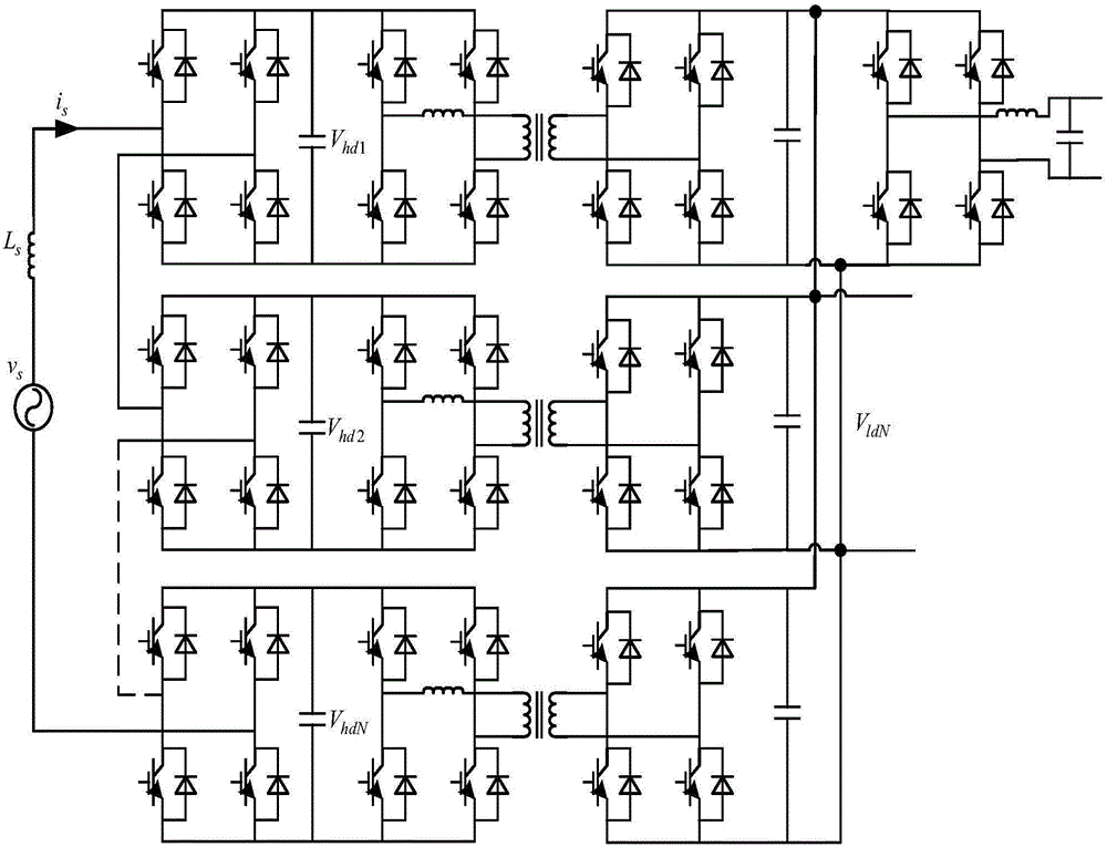
[0018] The invention discloses a method for controlling voltage and power balance of a modular power electronic transformer. The main power circuit used in the method is composed of three stages: the input stage is a cascaded H-bridge converter, the isolation stage is an isolated DC / DC converter, The output stage is a DC / AC inverter; the input stage adopts multi-module series connection to realize the conversion from the high-voltage side AC to the high-voltage side DC; the isolation stage is composed of multiple DAB converter modules whose output ends are connected in parallel, and the output ends of each DAB module are connected in parallel Connected to the low-voltage DC busbar, the input terminal and the output terminal of the input stage are connected to the high-voltage DC busbar to realize the conversion from the high-voltage side DC to...


PUM


Abstract

The invention discloses a voltage and power balance control method for a modular power electric transformer. The power electric transformer to which the method is applied to comprises an input stage, an isolation stage and an output stage; the input stage adopts common duty ratio control based on single phase dp decoupling, so that stable control of high voltage side direct current voltage and flexible adjustment of sine and power factors of input current are achieved; the isolation stage adopts a voltage power double loop control strategy without a current sensor, the output voltage outer loop adjustment generates a unified reference value of each power inner loop, and the adjustment of each power inner loop generates a phase shifting angle of each module of the isolation stage; and two types of control strategies of the input stage and the isolation stage act synergistically, so that voltage and power balance of each module of the power electric transformer is achieved.

Description

technical field [0001] The invention relates to the application of power electronics technology in power systems, in particular to a voltage and power balance control method of a modularized power electronic transformer. Background technique [0002] Power transformers have been used for more than a hundred years. Because of their high reliability and simple structure, they occupy an important position in today's power transmission and distribution systems, and their applications are huge. However, its main function is to achieve basic voltage level conversion and electrical isolation, and its functions are relatively single, and there are a series of disadvantages: large volume and weight; insulating oil poses a threat to the environment; it cannot maintain output voltage stability and improve power quality. [0003] The concept of power electronic transformer was proposed as early as the 1970s, mainly through power electronic technology and magnetic coupling technology to ...

Claims


Application Information

Patent Timeline
Patent Type & Authority Applications(China)
IPC IPC(8): H02J3/26H02M5/458H02M3/335
CPCY02E40/50
Inventor 盘宏斌肖志勇
Owner XIANGTAN UNIV
Why Eureka
Try Eureka