Medium-voltage distributed reactive power optimization system and method

A distributed, medium-voltage technology, applied in reactive power compensation, system integration technology, information technology support systems, etc., can solve problems such as frequent switching of devices, switching oscillations, and inability to correctly reflect the reactive power demand of feeders, achieving Improve the voltage quality, improve the power factor, reduce the effect of line loss

Active Publication Date: 2016-04-13
STATE GRID FUJIAN ELECTRIC POWER CO LTD +3
View PDF3 Cites 1 Cited by
  • Summary
  • Abstract
  • Description
  • Claims
  • Application Information

AI Technical Summary

Problems solved by technology

However, in the actual installation and application of this technology, the installation point is usually selected on the outgoing line side of the power transmission end, and this point in the line cannot reflect the overall load situation of the grid line at all, which causes the reactive power compensation device to improve the output voltage. When , the effect of improving the voltage at the end of the feeder line is not good
At the same time, the installation point cannot correctly reflect the reactive power demand of the entire feeder, and cannot correctly provide the judgment conditions for switching capacitors. When the reactive component of the load at the rear end of the installation point is smaller than the capacity of the compensation capacitor, the reactive power flow will flow to the power supply end , at this time, the controller in the reactive power compensation device will misjudge it as "overcompensation" and quit the operation of the compensation capacitor; Frequent switching of the device, easy to produce switching oscillation

Method used


Image

  • Medium-voltage distributed reactive power optimization system and method
  • Medium-voltage distributed reactive power optimization system and method
  • Medium-voltage distributed reactive power optimization system and method

Examples


Embodiment Construction

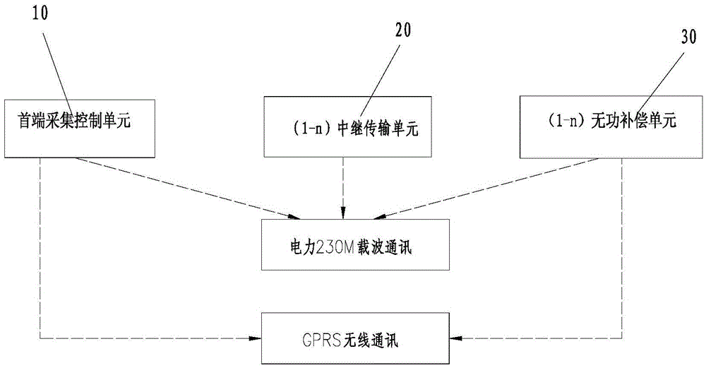
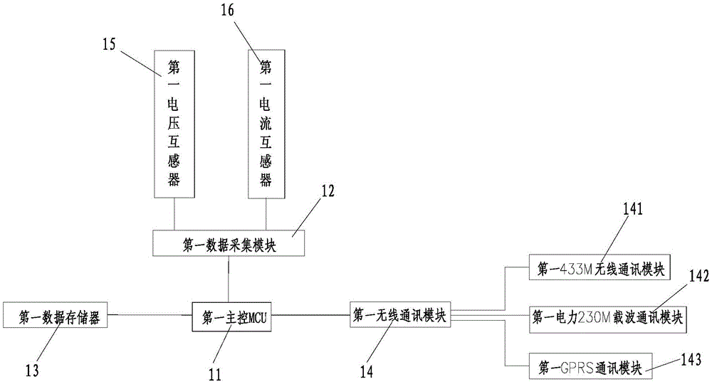
[0031] like figure 1 As shown in FIG. 1 , the functional block diagram of the communication between the head-end acquisition control unit, the relay transmission unit and the reactive power compensation unit in the embodiment of the present invention. The system includes a head-end collection control unit 10, (1-n) relay transmission unit 20, (1-n) reactive power compensation unit 30; head-end collection control unit 10 and (1-n) reactive power compensation unit 30 pass The GPRS wireless module is connected, and can also form an autonomous network with the (1-n) relay transmission unit 20, and use the carrier transmission of the power 230M frequency band as a communication method to ensure reliable communication of the equipment; wherein the head-end acquisition control unit 10 can use existing technology , can also be used as figure 2 Shown structural composition, (1-n) relay transmission unit 20 adopts prior art, the preferred relay signal amplifier of the present inventio...


PUM


Abstract

The invention discloses a medium-voltage distributed reactive power optimization system and method. The system comprises a head-end collection control unit, a plurality of reactive power compensation units and a background master station, wherein the head-end collection control unit is arranged at the position of the head end of a feeder; the reactive power compensation units are arranged in feeder branches; the collection control unit and the reactive power compensation units are in wireless communication connection; the head-end collection control unit and the background master station are in wireless communication connection; the reactive power compensation units and the background master station are in wireless communication connection; voltage and current signals of the head end of the feeder and the feeder branches and calculated real-time data result are imported back to the background master station; and the background master station controls switching of the reactive power compensation units according to reactive power flow analysis, formed topological structure map of a distribution network feeder and the load distribution condition, so that voltages at the head end and the tail end of a feeder line are balanced; the voltage quality of the feeder branches is improved; and the power factor is improved.

Description

technical field [0001] The invention relates to a device for adjusting, eliminating or compensating reactive power in a network, in particular to a medium-voltage distributed reactive power optimization system and method. Background technique [0002] In rural power distribution lines, due to the lack of reactive power compensation, the line loss is large and the voltage quality is poor. Usually, this situation needs to be changed. The measure taken is to install reactive power compensation devices on the distribution lines. By installing a reactive power compensation device, reactive power compensation can be effectively performed on the line, thereby achieving the purpose of energy saving and loss reduction. However, in the actual installation and application of this technology, the installation point is usually selected on the outgoing line side of the power transmission end, and this point in the line cannot reflect the overall load situation of the grid line at all, whi...

Claims


Application Information

Patent Timeline
IPC IPC(8): H02J3/18H02J13/00
CPCH02J13/0075H02J3/1864Y02E40/30Y04S10/22Y02E40/70Y02E60/00Y04S10/50Y04S40/126
Inventor 蔡晓军杨帆许梦黔陈志坚陈超锋苏毅伟吴玉煌曹发彦李杨杰熊军张华东彭晖陈荣
Owner STATE GRID FUJIAN ELECTRIC POWER CO LTD
Why Eureka
Try Eureka