Five-level half bridge inverter topology with high voltage utilization ratio

Active Publication Date: 2019-06-04
WANG HONGLIANG +1
View PDF4 Cites 0 Cited by
  • Summary
  • Abstract
  • Description
  • Claims
  • Application Information

AI Technical Summary

Benefits of technology

This patent describes a new type of inverter circuit that outputs five different levels of voltage. This circuit has a half-bridge inverter with a special capacitor that helps achieve high efficiency and reduces costs. The circuit also eliminates leakage current and allows for equal voltage on the two DC power supplies. The technical effect of this invention is a more efficient and cost-effective way to output multiple levels of voltage.

Problems solved by technology

The high frequency leakage current in the loop circuit leads to electromagnetic interference, and at the same time, it is dangerous to devices and human.
So the high frequency leakage current becomes a critical issue to be solved for the transformerless inverter system.
But it is difficult for the full bridge inverter to cancel substantially the high frequency leakage current because of the parasitic parameters within the inverter system.
However, its cost is high because the two AC filtering inductors' magnetic cores are not common for the symmetry mode.
In addition, cost is high because of double AC filtering inductors.
This additional circuit reduces the system efficiency and increases the system cost.

Method used


Image

  • Five-level half bridge inverter topology with high voltage utilization ratio
  • Five-level half bridge inverter topology with high voltage utilization ratio
  • Five-level half bridge inverter topology with high voltage utilization ratio

Examples


Embodiment Construction

[0094]Provided herein is five-level inverter topology. For a better understanding of the invention, and to show more clearly how it may be carried into effect, embodiments will be described in detail with reference of the accompanying drawings. Of course, the embodiments described below are part of the invention examples, not all of them. Those skilled in the art will recognize or be able to ascertain variants of the embodiments described herein. Such variants are within the scope of the invention and are covered by the appended claims.

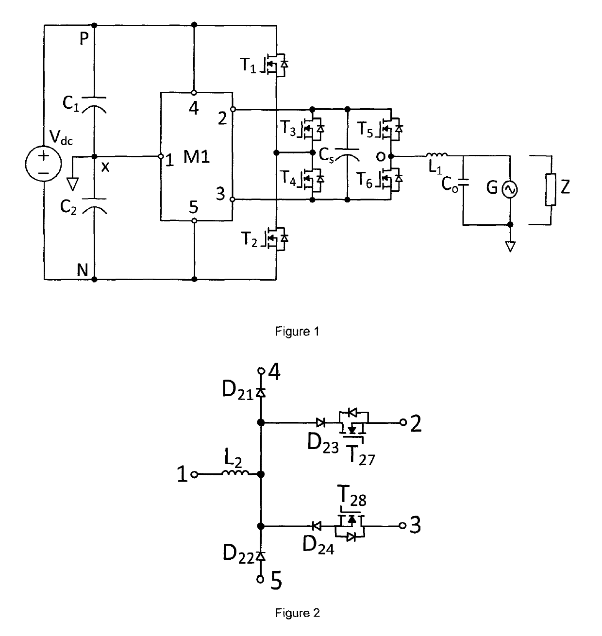
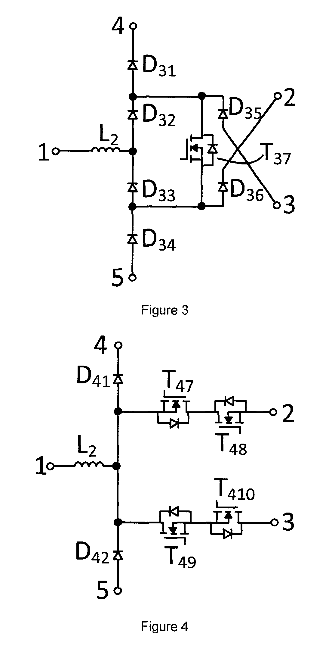
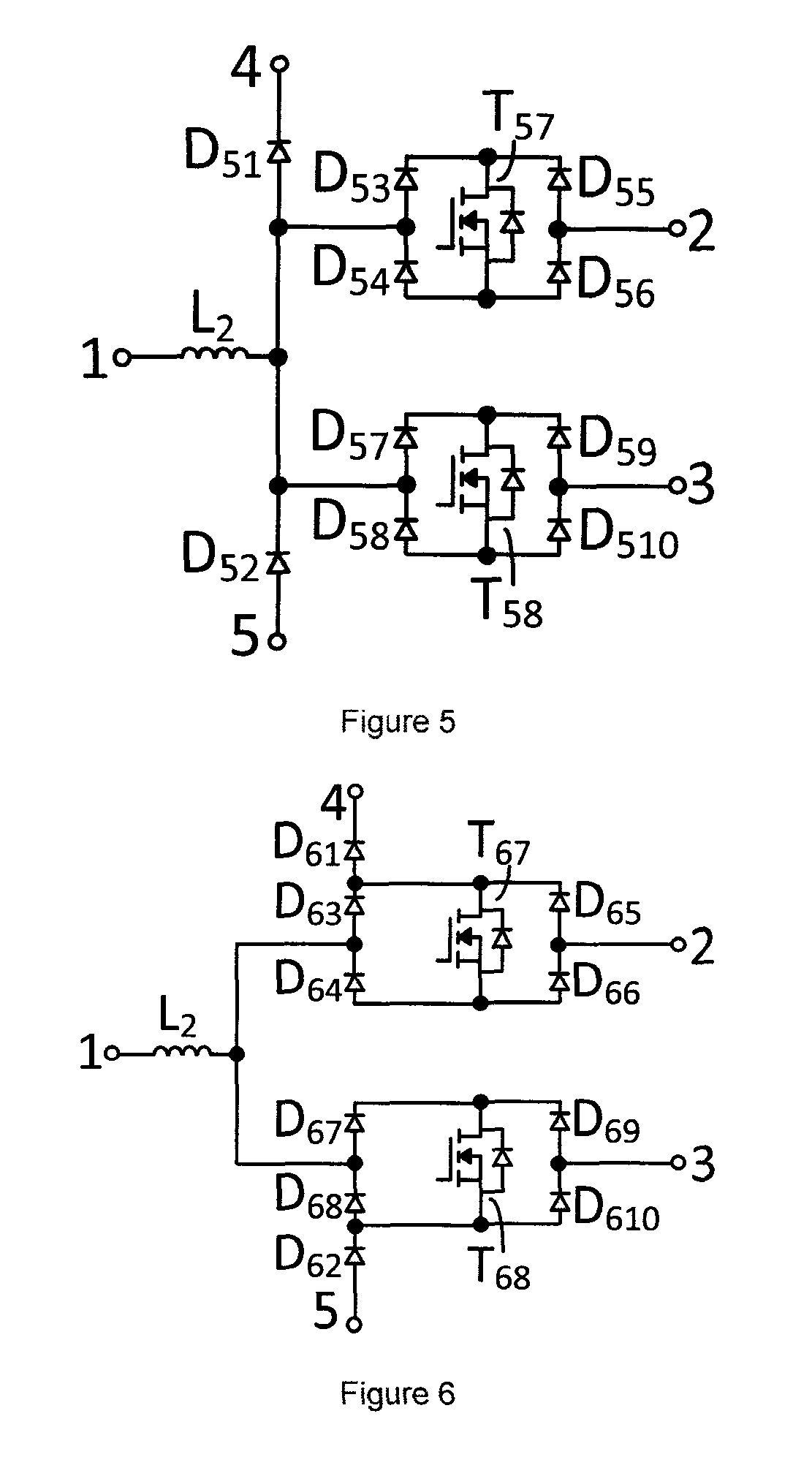
[0095]As shown in figures below, the term Vdc is DC power supply voltage, M1 or M2 is the circuit module in the half-bridge inverter circuit, C1 is a first capacitor which acts as the first DC power supply, C2 is a second capacitor which acts as the second DC power supply and Cs is the floating capacitor.

[0096]For the purpose of this description in the invention, the ratio of the peak-peak value of AC output voltage from inverter to the minimum DC inp...


PUM


Abstract

A single phase five-level inverter topology comprising a half-bridge inverter circuit with a floating capacitor which outputs five mutually different voltage levels including zero, wherein both the system cost and the size is reduced, the leakage current is eliminated substantially and high efficiency is achieved by using five-level half-bridge structure with only one AC filtering inductor. A three-phase five-level inverter topology wherein the voltage utilization is twice that of the present three-phase five-level half-bridge inverter under the same operating conditions; the AC filtering inductance is smaller than that of the three-level half-bridge inverter; the DC link mid-point voltage can be balanced without additional circuitry.

Description

RELATED APPLICATIONS[0001]This application is a 35 U.S.C. 371 of International Application No. PCT / CN2016 / 095363, filed on Aug. 15, 2016, and claims the benefit of the filing date of U.S. Application No. 62 / 205,647, filed on Aug. 14, 2015, the contents of both applications being incorporated herein by reference in their entirety.FIELD OF THE INVENTION[0002]The invention relates to power converter topology, especially to five-level inverter topology.BACKGROUND[0003]With the increasing threat of global energy and serious environmental problem, the renewable energy has been developing fast. Photovoltaic industry has an extensive future as its resources are plentiful and widespread. It is an important issue to lower cost and improve efficiency for photovoltaic system.[0004]It is known that photovoltaic arrays yield DC power. Inverter is used to convert DC from photovoltaic arrays into AC in photovoltaic system. There is a common mode loop circuit in the photovoltaic inverter system with...

Claims


Application Information

Patent Timeline
IPC IPC(8): H02M7/5387H02M7/487H02S40/32H02M7/483
CPCH02M7/483H02S40/32H02M7/5387H02M7/487Y02E10/50H02M1/0095H02M7/4837
Inventor WANG, HONGLIANGLIU, YAN-FEI
Owner WANG HONGLIANG
Why Eureka
Try Eureka