
PWM/PFM control circuit

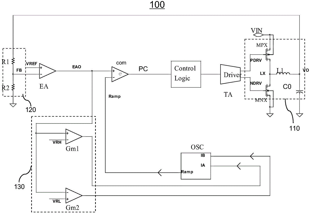
A technology for controlling circuits and control modes, applied in the direction of control/regulation systems, electrical components, and adjustment of electrical variables, which can solve the problems of large switching losses and achieve the effects of reducing power consumption and continuous switching transitions

Active Publication Date: 2015-10-21
WUXI ZGMICRO ELECTRONICS CO LTD
View PDF14 Cites 25 Cited by
  • Summary
  • Abstract
  • Description
  • Claims
  • Application Information

AI Technical Summary

Problems solved by technology

However, according to this principle, it can be seen that the maximum time difference length is equal to the high level time of PFM control signal A (ie, the minimum on-time), and the longest time generally does not exceed half of the oscillator cycle time in PWM mode. Therefore, frequency reduction The maximum value is 1.5 times the oscillator period in PWM mode, that is, the frequency is reduced to 1 / 1.5=2 / 3 times the oscillation frequency in PWM mode, which leads to the average value of switching loss under light load is still large, and the maximum The limit case is no load, in order to further reduce the standby power consumption under lighter load or no load, it is necessary to further reduce the minimum frequency value in PFM mode

Method used


Image

  • PWM/PFM control circuit
  • PWM/PFM control circuit
  • PWM/PFM control circuit

Examples


Embodiment Construction

[0022] The detailed description of the present invention directly or indirectly simulates the operation of the technical solution of the present invention mainly through programs, steps, logic blocks, processes or other symbolic descriptions. In the ensuing description, numerous specific details are set forth in order to provide a thorough understanding of the present invention. Rather, the invention may be practiced without these specific details. These descriptions and representations herein are used by those skilled in the art to effectively convey the substance of their work to others skilled in the art. In other words, for the purpose of avoiding obscuring the present invention, well-known methods and procedures have not been described in detail since they have been readily understood.

[0023] Reference herein to "one embodiment" or "an embodiment" refers to a particular feature, structure or characteristic that can be included in at least one implementation of the pres...


PUM


Abstract

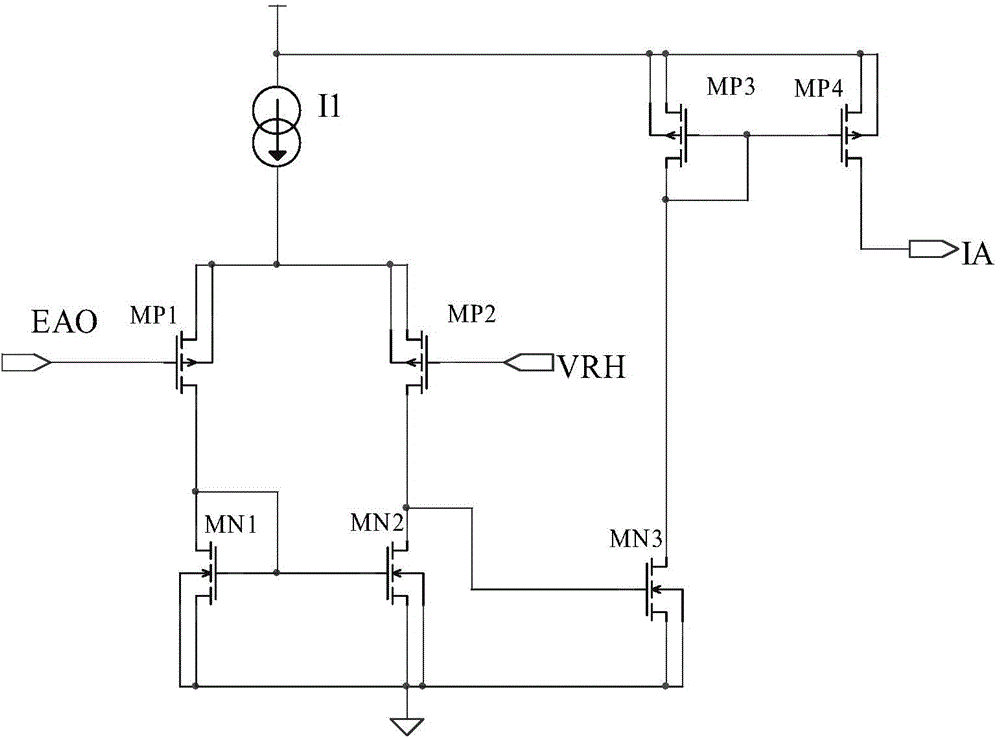
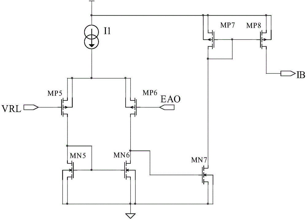
The invention provides a PWM / PFM control circuit comprising a feedback circuit, an error amplifier, a PWM comparator, an oscillator, and an oscillator frequency control circuit. The feedback circuit samples an output voltage of a power conversion circuit, and generates a feedback voltage reflecting the output voltage. The error amplifier obtains an error amplification voltage based on the error between a reference voltage and the feedback voltage. The oscillator generates a triangular wave oscillation signal. The PWM comparator is used for comparing the triangular wave oscillation signal and the error amplification voltage to output a control signal. The oscillator frequency control circuit outputs a corresponding current signal to the oscillator based on the error amplification voltage. The oscillator adjusts the magnitude of the charging current of the oscillator based on the current signal in order to change the frequency of the triangular wave oscillation signal output by the oscillator. Compared with the prior art, the PWM / PFM control circuit of the invention not only can realize continuous switching transition from PFM to PWM, but also can further reduce the minimum value of frequency under a PFM mode.

Description

【Technical field】 [0001] The invention relates to the field of power management circuits, in particular to a PWM / PFM control circuit in a switching power converter circuit. 【Background technique】 [0002] Now many switching power converters (for example, step-down DC-DC converters) include two working modes: PWM (Pulse Width Modulation) mode and PFM (Pulse Frequency Modulation) mode. Generally, when the load is heavy, the switching power converter works in PWM mode, so that it works at a fixed higher frequency and maintains a lower output voltage ripple. However, since the switching loss of the control circuit is generally large in PWM mode, usually when the load is light, the switching power converter switches to work in PFM mode. As the load becomes lighter, its operating frequency becomes lower, and the control circuit The average value of switching losses becomes lower as the frequency decreases. Because the traditional control circuit compatible with PWM mode and PFM ...

Claims


Application Information

Patent Timeline
Patent Type & Authority Applications(China)
IPC IPC(8): H02M3/156H02M1/08
CPCY02B70/10
Inventor 王钊
Owner WUXI ZGMICRO ELECTRONICS CO LTD
Learn More