Plate type integral heat pipe for heat dissipation of electromagnetic iron remover

An electromagnetic iron remover and plate-type technology, which is applied in the field of enhanced heat transfer, can solve the problems of excessive consumption of metal materials, complex processing and installation of heat pipes, and complicated installation

Active Publication Date: 2017-06-20
CHANGSHA UNIVERSITY OF SCIENCE AND TECHNOLOGY
View PDF5 Cites 0 Cited by
  • Summary
  • Abstract
  • Description
  • Claims
  • Application Information

AI Technical Summary

Problems solved by technology

The analysis found that the patent has the following deficiencies: first, there is the thermal resistance of the aluminum plate; second, there is the contact thermal resistance between the heat pipe and the aluminum plate; third, the aluminum plate needs a half-moon arc groove and many screw holes, and the processing and installation are relatively complicated; four. The heat dissipation fins and the condensation section are installed nestedly, the installation is more complicated, and there is contact thermal resistance between the metals; the fifth is that the thickness of the heat conduction plate is uneven, which will cause slightly uneven temperature of the coil
The analysis found that the patent has the following deficiencies: first, the processing and installation of heat pipes with concave-convex structures are more complicated; second, there are both contact thermal resistance and metal thermal resistance in the interlocking part; third, the plane after interlocking cannot guarantee a better plane The fourth is that the consumption of metal materials is more
The heat pipe heat dissipation technology proposed in Chinese patent 88105470.4 is characterized in that multiple heat pipes are vertically inserted into the coil, and the gaps around the heat pipes are filled with thermally conductive fillers. Compared with metal, it is still a poor conductor and has a large thermal resistance; the heat pipe protrudes from the upper part of the iron remover, which is not conducive to natural heat dissipation
Its shortcomings are as follows: first, it is difficult to solve the sealing problem of the lead wires of the coil, thereby destroying the vacuum degree of the heat pipe; second, the aluminum condensation section and the steel intermediate partition are not easy to weld; third, the tubular array condensation section is vertically drawn from the upper part of the iron remover , not conducive to natural convection heat dissipation
[0009] It can be seen from the above-mentioned published technical documents that due to the defects of the heat pipe structure in the prior art, the heat pipe heat dissipation technology of the electromagnetic iron remover currently researched and developed still has problems such as poor heat dissipation effect, high temperature, and uneven temperature. The common defects are: 1. There are many additional thermal resistances, such as metal thermal resistance, contact thermal resistance, filler thermal resistance, etc., which lead to a decrease in the heat dissipation performance of the heat pipe, and the heat dissipation effect is not good; In the electromagnetic coil of ironware, the actual heat dissipation process is that each heat pipe operates independently, and there is no match or complementarity between them, resulting in the quality of local heat dissipation in the electromagnetic coil, which is completely determined by the heat dissipation effect of the heat pipe located there. The electromagnetic coil itself has a phenomenon of uneven heating. Therefore, the temperature in the local area with a large heat generation in the electromagnetic coil continues to maintain a high level, which affects the normal use of the electromagnetic coil. In severe cases, the electromagnetic coil is burned.

Method used


Image

  • Plate type integral heat pipe for heat dissipation of electromagnetic iron remover
  • Plate type integral heat pipe for heat dissipation of electromagnetic iron remover
  • Plate type integral heat pipe for heat dissipation of electromagnetic iron remover

Examples


Embodiment 1

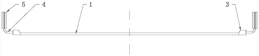
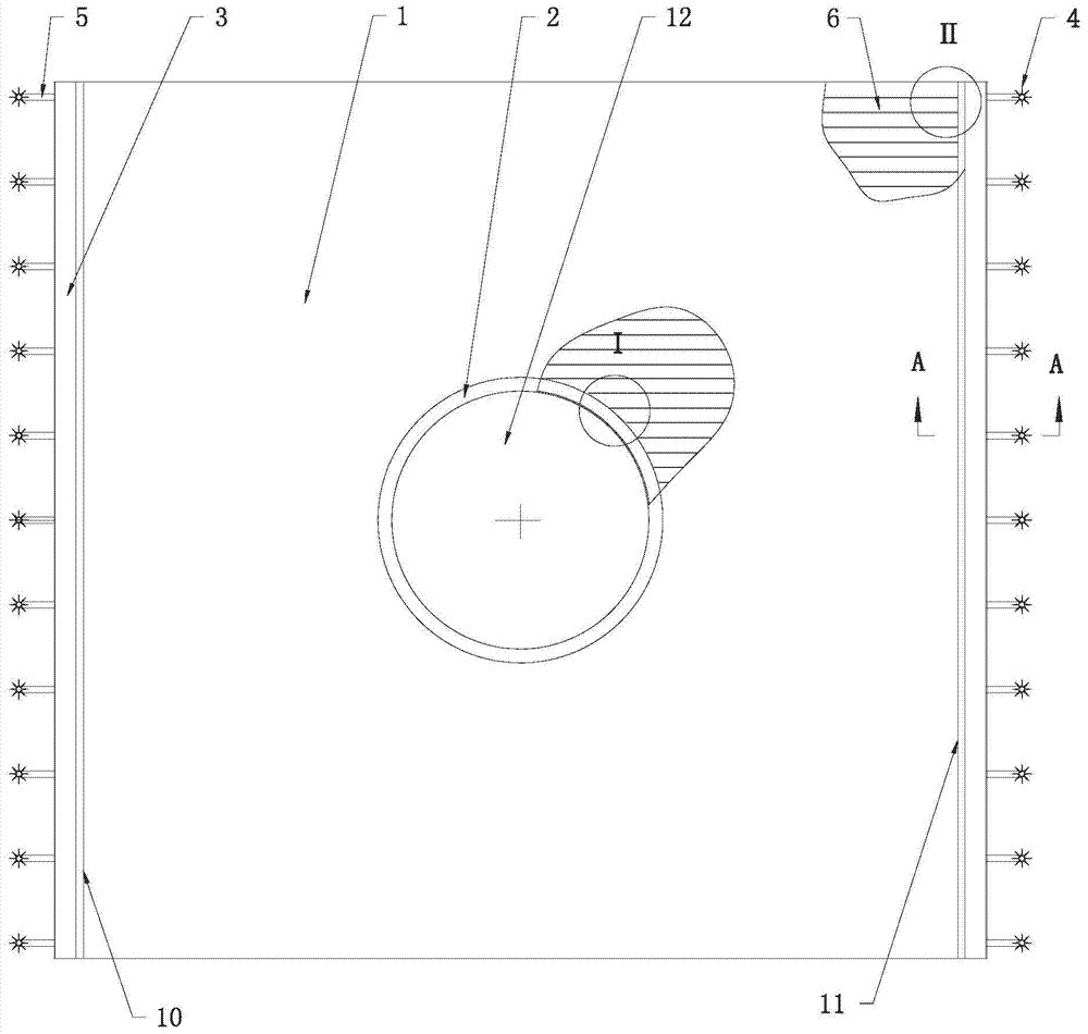
[0044] See attached figure 1 , 2 , 3, 4, 5, a plate-type integral heat pipe for heat dissipation of an electromagnetic iron remover, the plate-type integral heat pipe includes a rectangular flat plate 1, and evaporation channels 6 parallel to each other are evenly distributed on the rectangular flat plate 1, and the The evaporation channel 6 is located between the upper and lower surfaces of the rectangular flat plate 1, and its axis is parallel to the upper and lower surfaces of the rectangular flat plate 1; Extending and passing through the second side 11 parallel to the first side; a through hole 12 is provided in the center of the rectangular flat plate 1, and the axis of the through hole 12 is perpendicular to the upper and lower surfaces of the rectangular flat plate 1;

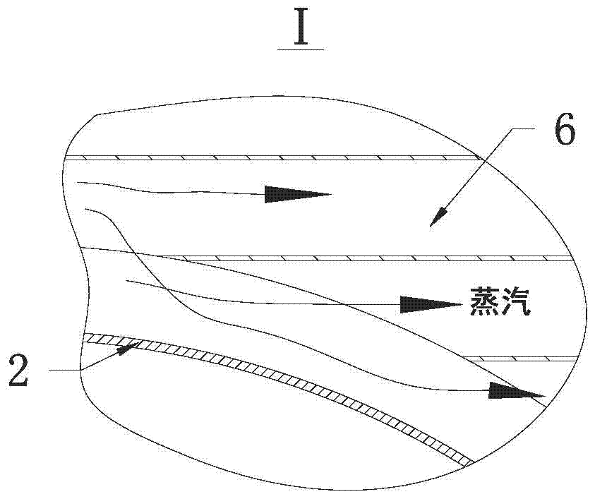
[0045] A hollow ring 2 is provided on the circumference of the through hole 12, and the evaporation channel 6 passing through the circumference of the through hole 12 communicates with the inner cavity...

Embodiment 2

[0060] See attached Figure 6 In this embodiment, the plate-type integral heat pipe is cut into two pieces through the center of the through hole 12 on the longitudinal section parallel or perpendicular to the axis of the evaporation channel 6, and each of the monomers has an evaporation channel port 13 An equalizing tube 7 is arranged on the section of the cutout, and one end of the equalizing tube 7 is closed, and the other end communicates with the hollow ring 2, and its side communicates with the port 13 of the evaporation channel passing through the section of the cutout.

[0061] In this embodiment, the thickness of the rectangular plate is 30mm;

[0062] In this embodiment, the cross-section of the evaporation channel or steam distribution pipe is square;

[0063] The cross-sectional area of ​​the evaporation channel is 1200mm 2 ;

[0064] The cross-sectional area of ​​the steam distribution pipe is 6 times the cross-sectional area of ​​the evaporation channel;

[0...

Embodiment 3

[0072] See attached Figure 7 , in this embodiment, the plate-type integral heat pipe is cut into four individual pieces through the center of the through hole 12 on a longitudinal section parallel to or perpendicular to the axis of the evaporation channel 6, each of which has an evaporation channel port 13 An equalizing tube 7 is arranged on the section of the cutout, and one end of the equalizing tube 7 is closed, and the other end communicates with the hollow ring 2, and its side communicates with the port 13 of the evaporation channel passing through the section of the cutout.

[0073] In this embodiment, the thickness of the rectangular plate is 50mm;

[0074] In this embodiment, the cross-section of the evaporation channel or steam distribution pipe is rectangular;

[0075] The cross-sectional area of ​​the evaporation channel is 2000mm 2 ;

[0076] The cross-sectional area of ​​the steam distribution pipe is 9 times the cross-sectional area of ​​the evaporation chann...


PUM


Abstract

A plate-type integral heat pipe for heat dissipation of an electromagnetic iron remover, comprising a rectangular flat plate, on which there are evenly distributed evaporation channels parallel to each other, and the evaporation channels are located between the upper and lower surfaces of the rectangular flat plate. The axis is parallel to the upper and lower surfaces of the rectangular flat plate; a through hole is arranged in the center of the rectangular flat plate, and the axis of the through hole is perpendicular to the upper and lower surfaces of the rectangular flat plate; Hollow ring, the evaporation channel running through the circumference of the through hole communicates with the inner cavity of the hollow ring; the first side and the second side of the rectangular flat plate are respectively provided with steam distribution pipes, and the steam distribution pipes are two A hollow tube with a closed end, the evaporation channel port on the first side or the second side communicates with the inner cavity of the steam distribution tube arranged on the corresponding side; each steam distribution tube is provided with a Straight finned tubes. The invention has simple and reliable structure, strong heat transfer capacity and high cost performance. Compared with the radiator composed of independent multi-heat pipes, it has stronger heat dissipation capacity, better temperature uniformity effect, higher processing and installation efficiency, and lower Generates cost and is suitable for industrial application.

Description

technical field [0001] The invention discloses a plate-type integral heat pipe for heat dissipation of an electromagnetic iron remover, belonging to the technical field of heat transfer enhancement. [0002] technical background [0003] Electromagnetic iron remover is a device that uses strong magnetic attraction to remove ferromagnetic impurities on material conveyor belts. The equipment and its cleaning work have the following functions: first, to protect the conveyor belt from being damaged by ferromagnetic impurities; second, to ensure the safe and stable operation of follow-up equipment, such as crushers, grinders, boilers, etc.; third, to ensure or improve related products Quality, if the ferromagnetic impurities are not removed, the color of ceramic products will be seriously affected; the fourth is to improve the quality of port material transportation to meet customer requirements. Based on the function of electromagnetic iron remover, this equipment is widely used...

Claims


Application Information

Patent Timeline
Patent Type & Authority Patents(China)
IPC IPC(8): H05K7/20
Inventor 夏侯国伟
Owner CHANGSHA UNIVERSITY OF SCIENCE AND TECHNOLOGY
Why Eureka
Try Eureka