Power equipment cooling circulation device

A cooling cycle and power equipment technology, applied in the field of power equipment, can solve the problems of reducing the service life of power equipment, rusting of power equipment, short circuit of power equipment, etc., to save resources, speed up the rate of heat absorption, and reduce the effect of bearing capacity

Inactive Publication Date: 2015-10-21
王学香
View PDF4 Cites 2 Cited by
  • Summary
  • Abstract
  • Description
  • Claims
  • Application Information

AI Technical Summary

Problems solved by technology

And because a large amount of water vapor will be generated during water cooling, the water vapor entering the power equipment may cause a short circuit, and the power equipment will rust in the long run, reducing the service life of the power equipment, thereby increasing the cost

Method used


Image

  • Power equipment cooling circulation device
  • Power equipment cooling circulation device
  • Power equipment cooling circulation device

Examples


Embodiment Construction

[0014] The technical solutions in the embodiments of the present invention will be described clearly and completely below in conjunction with the accompanying drawings in the embodiments of the present invention. Apparently, the described embodiments are only some, not all, embodiments of the present invention. Based on the embodiments of the present invention, all other embodiments obtained by persons of ordinary skill in the art without making creative efforts belong to the protection scope of the present invention.

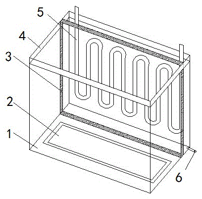
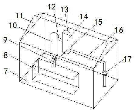
[0015] see Figure 1-3 , the present invention provides a technical solution: a cooling cycle device for power equipment, including a first box 1, a groove 2, a moisture absorption plate 3, a partition 4, a heat absorption pipe 5, a drain pipe 6, and a second box 7 The first The casing 1 and the second casing 7 are separated by a partition plate 4 in the middle, and the water inlet pipe 9 and the water extraction pipe 16 in the second casing 7 are connected to...


PUM


Abstract

The invention discloses a power equipment cooling circulation device, which comprises a first box body, a groove, a moisture-absorbing plate, a partition plate, a heat-absorbing pipe, a water drain pipe, a second box body, a storage battery, a water inlet pipe, a water storage tank, a top cover, a communicating pipe, a cover, a condensing tank, a water shut-off valve, a water pumping pipe, a pump body and solar photovoltaic panels, wherein the first box body and the second box body are separated by the partition plate arranged in the middle, the water inlet pipe and the water pumping pipe in the second box body are connected with two ends of the heat-absorbing pipe in the first box body respectively, the condensing tank and the water storage tank are connected between the water inlet pipe and the water pumping pipe, the condensing tank and the water storage tank are connected through the communicating pipe, the storage battery is arranged in the second box body, the moisture-absorbing plate is arranged in the first box body, the groove is formed in the bottom part of the first box body, and the bottom part of the first box body is provided with the water drain pipe. The power equipment cooling circulation device adopts the method of absorbing heat through a liquid, can absorb heat produced by power equipment quickly, prevents water vapor produced during heat absorption from entering into the power equipment, and is very practical.

Description

technical field [0001] The invention relates to the technical field of electric equipment, in particular to a cooling cycle device for electric equipment. Background technique [0002] With the development of electronic power, the power of the power module is getting bigger and bigger, its heating power is also getting bigger and bigger, the heat flux density of the module is also getting bigger and bigger, and the cooling method of the power module is gradually changing from natural cooling method, profile The radiator cooling method and the heat pipe cooling method have developed into the water-cooling cooling method; and the water-cooling plate cooling method is the most used in the current water-cooling cooling method. The water cooling plate is to process or assemble the water channel in the metal plate, process the heat dissipation fins in the water channel, and install the power module on the surface of the water cooling plate. During operation, the cooling water flo...

Claims


Application Information

Patent Timeline
Patent Type & Authority Applications(China)
IPC IPC(8): H05K7/20
Inventor 王学香
Owner 王学香
Why Eureka
Try Eureka