
Supporting system for turbine part of gas turbine engine

A technology of supporting system and gas turbine, applied in the directions of engine components, machines/engines, blade supporting components, etc., can solve the problems of easy cracking and high cost of bearing support plates, avoid cost increases, and solve the problem of easy cracking. , to ensure the effect of structural life and reliability

Inactive Publication Date: 2015-10-28
CHINA AVIATION POWER MACHINE INST
View PDF5 Cites 7 Cited by
  • Summary
  • Abstract
  • Description
  • Claims
  • Application Information

AI Technical Summary

Problems solved by technology

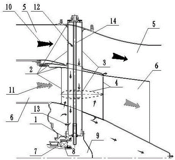
[0005] The technical problem to be solved by the present invention is to overcome the technical problems that the load-bearing support plate in the existing support system is prone to cracks through the high-temperature passage, and the cost of using a high-temperature-resistant alloy material for the sluggish load-bearing support plate to resist harsh environments is high, and to provide a gas-fired The support system of the turbine parts of the turbine engine, based on the optimized setting of the system structure, ensures that the working environment of the load-bearing support plate is improved, the cooling effect is good, and the service life is long, which can avoid blindly using high-temperature-resistant alloy materials to make the cost lower

Method used


Image

  • Supporting system for turbine part of gas turbine engine
  • Supporting system for turbine part of gas turbine engine
  • Supporting system for turbine part of gas turbine engine

Examples


Embodiment Construction

[0023] The embodiments of the present invention will be described in detail below with reference to the accompanying drawings, but the present invention can be implemented in many different ways defined and covered by the claims.

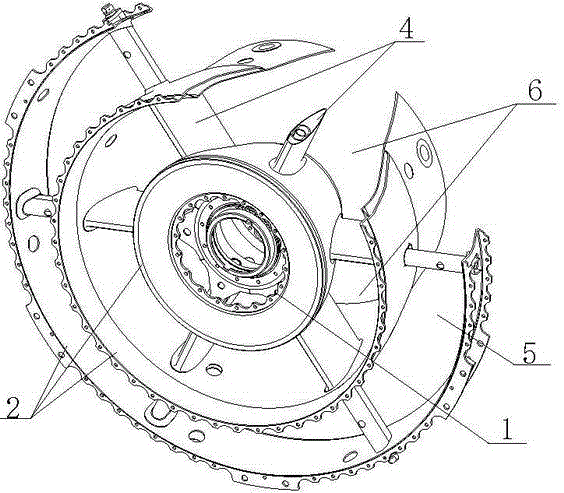
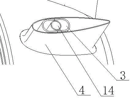
[0024] Such as figure 1 with figure 2 As shown, the present invention provides a support system for turbine components of a gas turbine engine. The support system includes a bearing block 1, a load-bearing casing 2, and a plurality of circumferentially evenly distributed bearing blocks 1 and the load-bearing casing 2. The load-bearing support plate 3; the load-bearing support plate 3 is a cavity structure, the part of the load-bearing support plate 3 located in the outer duct 5 is provided with an air inlet 12, and the load-bearing support plate 3 is opened with an outlet near the bearing seat 1 Air port 13; said load-bearing support plate 3 is provided with an aerodynamic leaf-shaped support plate 4 outside the part of the internal passage 6, suc...


PUM


Abstract

The invention provides a supporting system for a turbine part of a gas turbine engine. The supporting system comprises a bearing pedestal, a force bearing receiver and a plurality of force bearing supporting plates which are used for connecting the bearing pedestal and the force bearing receiver and are evenly distributed in the circumferential direction. Pneumatic blade type supporting plates are arranged outside the portions, located on an inner duct, of the force bearing supporting plates. The pneumatic blade type supporting plates are each of a cavity structure. The force bearing supporting plates are located in cavities of the pneumatic blade type supporting plates, and each pneumatic blade type supporting plate is provided with an air outlet. According to the supporting system, the portions, located in high-temperature and high-pressure gas, of the force bearing supporting plates are ingeniously provided with the pneumatic blade type supporting plates, and further, the pneumatic blade type supporting plates are arranged to be in the shape of wings; cooling gas coming from the inner cavities of the force bearing supporting plates can directly enter the pneumatic blade type supporting plates and has a cooling effect on the pneumatic blade type supporting plates; the inner sides and the outer sides of the force bearing supporting plates located in the inner cavities of the pneumatic blade type supporting plates are cooled; and besides, the pneumatic blade type supporting plates and gas located between the pneumatic blade type supporting plates and the force bearing supporting plates powerfully protect the force bearing supporting plates, and therefore the service life of the force bearing supporting plates is prolonged and the reliability of the force bearing supporting plates is improved.

Description

technical field [0001] The present invention relates to the field of turbine technology, and more particularly, to a support system for a turbine component of a gas turbine engine. Background technique [0002] For the rotor system of the gas turbine engine and the ground gas turbine, the working load needs to be transmitted to the external engine mounting joint through the load-bearing system. The load-bearing system of the rotor is usually composed of a bearing seat, a load-bearing support plate, and a load-bearing casing. The bearing seat is used to install the bearing and its cooling and lubricating structure; the load-bearing casing is connected to the engine mounting section through the external casing; the load-bearing support plate is used to connect the bearing seat and the load-bearing casing. The outer duct refers to the duct outside the air inlet, which is not connected to the combustion chamber; the inner duct refers to the duct inside the air inlet, which is c...

Claims


Application Information

Patent Timeline
Patent Type & Authority Applications(China)
IPC IPC(8): F01D5/02F01D25/28F01D25/12
Inventor 李鑫陈竞炜陶冶科付晟徐鲁兵白忠恺叶炜
Owner CHINA AVIATION POWER MACHINE INST
Learn More