Supercharge Your Innovation With Domain-Expert AI Agents!

Continuously Variable Transmission

A continuously variable transmission and input shaft technology, applied to transmission parts, belts/chains/gears, mechanical equipment, etc., can solve problems such as hindering the rotation of the pinion shaft and adverse effects of shifting actions, and achieve the effect of ensuring supply

Active Publication Date: 2015-10-28
HONDA MOTOR CO LTD
View PDF5 Cites 0 Cited by
  • Summary
  • Abstract
  • Description
  • Claims
  • Application Information

AI Technical Summary

Problems solved by technology

If the dirt accumulated on the thinned portion 52 increases, it will hinder the rotation of the pinion shaft, which may adversely affect the shifting operation.

Method used


Image

  • Continuously Variable Transmission
  • Continuously Variable Transmission
  • Continuously Variable Transmission

Examples


Embodiment Construction

[0024] Hereinafter, embodiments of the present invention will be described in detail with reference to the drawings. In addition, the embodiment described below is an example of the means for realizing the present invention, and the present invention can be applied to a configuration in which the following embodiments are modified or modified within a range that does not depart from the gist. In addition, it is self-evident that the continuously variable transmission of the present invention can also be applied to other applications than automobiles.

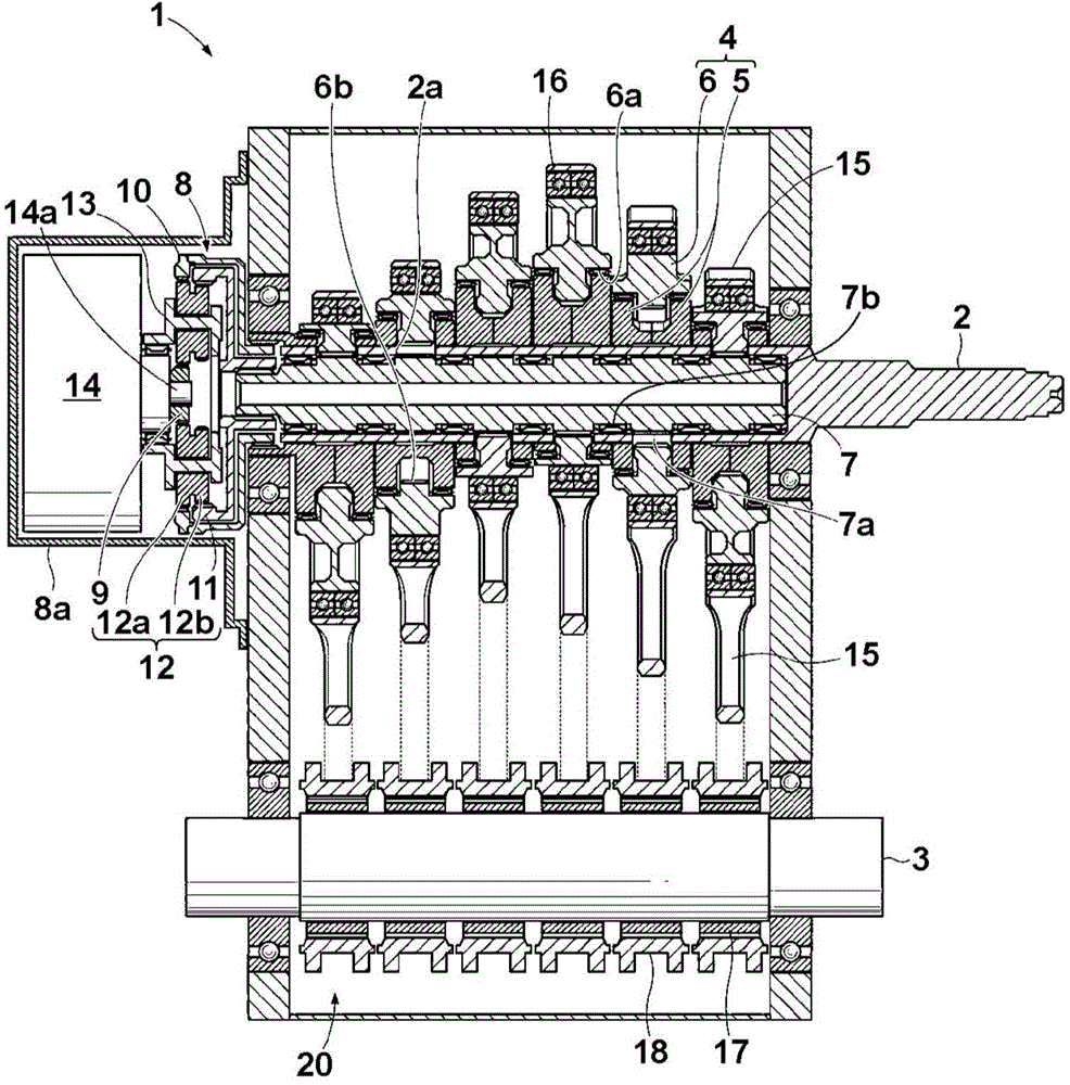
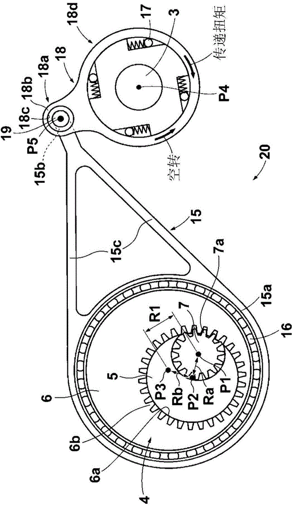
[0025] First, refer to figure 1 with figure 2 The structure of the continuously variable transmission of this embodiment will be described.

[0026] The continuously variable transmission 1 of the present embodiment is a transmission capable of setting the gear ratio i (i = the rotation speed of the input shaft / the rotation speed of the output shaft) to infinity (∞) and the rotation speed of the output shaft to "0", namely A kind...


PUM


Abstract

The invention provides a continuously variable transmission, which comprises an input shaft, an output shaft, a driving force inputting portion, a crank-link mechanism, and one-way rotation resisting mechanisms. The crank-link mechanism has an offset adjusting mechanism and connecting rods. The driving force input portion has cams, an eccentric component, and a pinion shaft, wherein the pinion shaft is supported in the input shaft via pinion bearings in a rotation manner; the eccentric component has a containing hole for containing the cams in a manner that the cams supporting the pinion shaft can rotate. Internal teeth engaging with external teeth of the pinion shaft are formed in the containing hole. The cams are arranged adjacent to each other in an axial direction in a manner that one cam holds the external teeth of the pinion shaft. A thinning portion is formed on a jointing face of the cams and is subject to cut for form space containing the external teeth of the pinion shaft. A communication path is formed in the thinning portion and has a first opening in an inner wall, near the external teeth, of the thinning portion, and a second opening in an outer wall, opposition to the external teeth, of the thinning portion.

Description

Technical field [0001] The invention relates to a dirt discharge structure of a continuously variable transmission of a four-section linkage mechanism type. Background technique [0002] For example, Japanese Patent Application Laid-Open No. 2013-36536 describes the following four-section link mechanism continuously variable transmission, which converts the rotation of the input shaft connected to the engine into the reciprocating motion of the connecting rod, and connects the transmission through a one-way clutch. The reciprocating movement of the rod is converted into the rotational movement of the output shaft. [0003] In the above-mentioned Japanese Patent Application Publication No. 2013-36536, the cam disc connected to the input shaft of the engine is such as Figure 7 As shown, a plurality of disk members are assembled by fastening them with bolts inserted in the axial direction. In addition, on the butt surfaces that fasten the cam discs to each other, such as Figure 6B A...

Claims


Application Information

Patent Timeline
IPC IPC(8): F16H37/12F16H57/04
CPCF16H37/124F16H57/042F16H57/0427F16H57/0467
Inventor 西村优史
Owner HONDA MOTOR CO LTD
Features
  • R&D
  • Intellectual Property
  • Life Sciences
  • Materials
  • Tech Scout
  • Unparalleled Data Quality
  • Higher Quality Content
  • 60% Fewer Hallucinations
Learn More