Improved system and method for transformer and reactor noise source positioning and vibration detection

A technology for vibration detection and transformers, which is applied in the field of reactor noise source location and vibration detection, and improved transformers. It can solve problems such as low precision, inability to measure transformers, reactor vibration signals, and limited array placement.

Active Publication Date: 2015-10-28
STATE GRID CORP OF CHINA +3
View PDF6 Cites 21 Cited by
  • Summary
  • Abstract
  • Description
  • Claims
  • Application Information

AI Technical Summary

Problems solved by technology

[0023] However, field experiments have found that the resolution of the low-frequency noise of the transformer and reactor body is not enough for this array. When localizing the sound source for the low-frequency noise signal of a large transformer, there are problems of ambiguous positioning and low accuracy. At the same time, there are problems of inability to synchronize Defects in measuring vibration signals of transformers and reactors
The main constraints are that the aperture of the array is too small, and the size of the large transformer is large (the cross-sectional size is about 5*6 meters). In order to cover the entire transformer cross-section, the array needs to be far away from the transformer, which reduces the resolution.
In addition, the site safety requirements of the substation are relatively high, and the placement of the array is often limited.

Method used


Image

  • Improved system and method for transformer and reactor noise source positioning and vibration detection
  • Improved system and method for transformer and reactor noise source positioning and vibration detection
  • Improved system and method for transformer and reactor noise source positioning and vibration detection

Examples


Embodiment Construction

[0054] The present invention will be described in further detail below based on specific embodiments and in conjunction with the accompanying drawings.

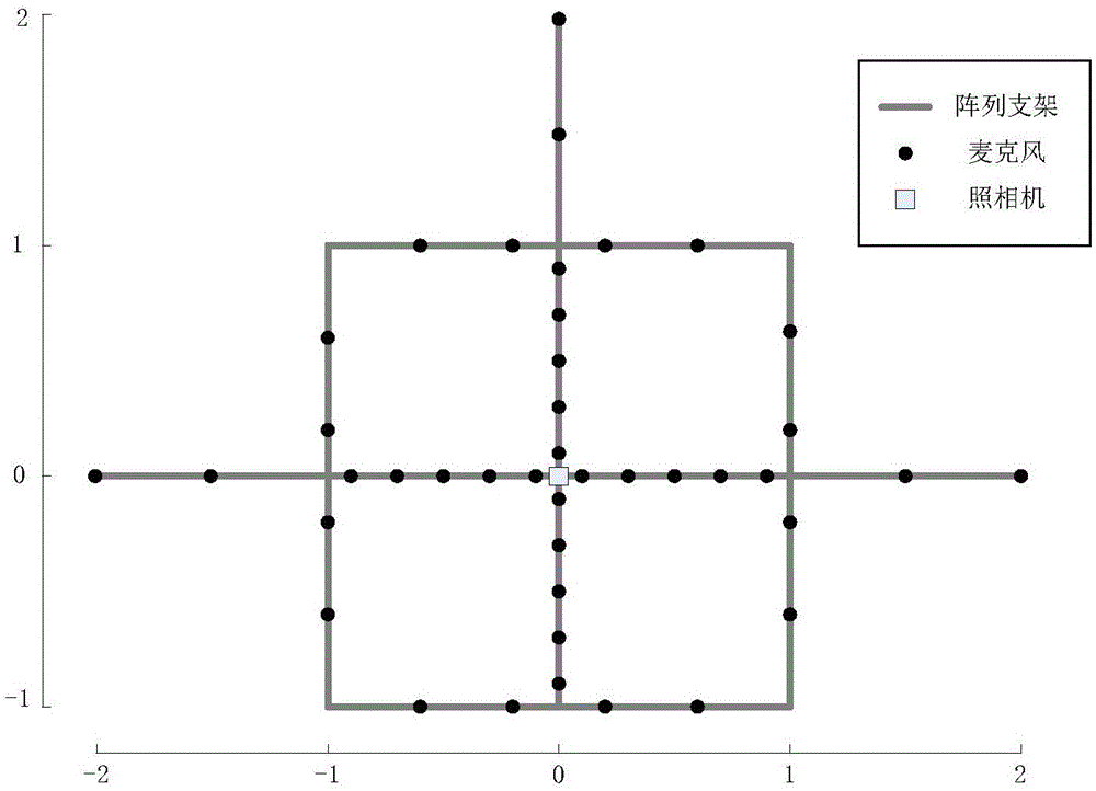
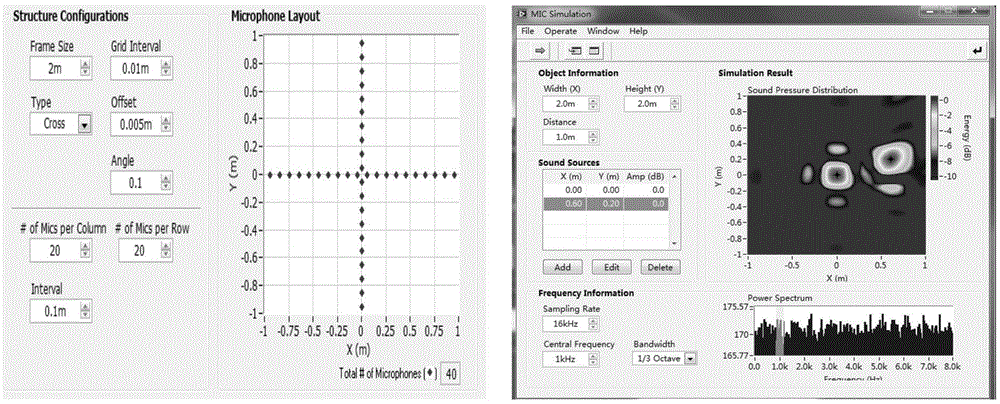
[0055] refer to Figure 1 ~ Figure 2 As shown, the improved transformer, reactor noise source location and vibration detection system of the present invention improves the layout of the microphones. On the basis of the original regular equidistant cross structure, it adopts a variable spacing design and adds horizontal and vertical microphones. The improved array aperture is expanded from the original 2m*2m to 4m*3m, which significantly improves the resolution of low-frequency sound. The distance between the microphones has been improved from the original 0.1m to 0.2, 0.4, 0.5m, etc. This irregularity has a significant effect on suppressing sidelobe ghosts and expanding the effective dynamic range of the array. The numerical simulation of the imaging results of the array is as follows: Figure 4 shown.

[0056] A specific ...


PUM


Abstract

The invention provides an improved system and a method for transformer and reactor noise source positioning and vibration detection. The system comprises a microphone support, a noise sensor array, a vibration sensor, a data acquisition system, a microphone array imaging module, a noise vibration testing module, and auxiliary equipment, the noise sensor array is formed by a plurality of microphones fixedly arranged on a microphone array support, the microphones are respectively arranged on a quartered square-shaped support and support rods led out from the left, right, and upper parts of the quartered square-shaped support, and the center of the quartered square-shaped array is provided with a camera for shooting photos of a detected object. The method includes steps: system building and connection; test system self-check; array position selection; array calibration; sound source positioning imaging; vibration measurement; and array dismounting. According to the system and the method, the quartered square-shaped microphone array is employed so that the precision of sound source positioning of the system for low-frequency-band noise signals is improved, vibration monitoring is additionally provided so that synchronous measurement of vibration signals and the noise signals is realized, and the positioning precision of the low-frequency-band noise sources of the transformer and the reactor is improved.

Description

technical field [0001] The invention relates to the field of condition maintenance of power transmission and transformation equipment, in particular to an improved transformer and reactor noise source location and vibration detection system and method, which realizes the positioning of the transformer and reactor noise source and simultaneously measures the transformer and reactor vibration signals. Background technique [0002] With the development of electric power industry, more and more people pay more and more attention to the harm caused by the noise and vibration of transformers and reactors. In recent years, the noise and vibration problems of large-scale UHV transformers and reactors have become more and more prominent, but domestic research in this field has been relatively small, and the experimental research on noise has basically stayed at the stage of measuring sound pressure level and frequency spectrum. These studies are far from It cannot meet the needs of i...

Claims


Application Information

Patent Timeline
Patent Type & Authority Applications(China)
IPC IPC(8): G01H1/12G01S5/18
Inventor 卢文华毛晋生潘永忠张海龙程林杜振波陈建杰方超杜玮钱江
Owner STATE GRID CORP OF CHINA
Why Eureka
Try Eureka