Quick and dynamic vacuum calibration method for vacuum gauge

A technology of dynamic calibration and calibration method, which is applied in the direction of measuring devices, instruments, and measuring fluid pressure, etc., which can solve the problems that are difficult to meet the application requirements of millisecond-level dynamic vacuum calibration, long valve opening and closing time, and large upstream chamber volume. Dynamic response evaluation ability, shortening the establishment time, and ensuring the effect of rapidity

Active Publication Date: 2015-10-28
LANZHOU INST OF PHYSICS CHINESE ACADEMY OF SPACE TECH
View PDF5 Cites 8 Cited by
  • Summary
  • Abstract
  • Description
  • Claims
  • Application Information

AI Technical Summary

Problems solved by technology

[0004] The advantage of this method is that it utilizes the advantages of fast response, high sensitivity, and non-contact of optical interferometry to measure the standard pressure of dynamic vacuum calibration. However, because the butterfly valve used in this device controls the dynamic expansion process of the system, in addition, Since the Michelson optical interferometer is placed in the upstream chamber, the volume of the upstream chamber is relatively large (about 2L), and in order to ensure a sufficiently small volume ratio (about 0.0025), the volume of the downstream chamber is also relatively large (about 800L). Due to the long closing time, the large volume of the system, the complex dynamic characteristics of rare gas, and the coupling between vacuum and temperature, the standard pressure establishment time of the device is still as short as 3s, which is still difficult to meet the application of millisecond-level dynamic vacuum calibration. need

Method used


Image

  • Quick and dynamic vacuum calibration method for vacuum gauge
  • Quick and dynamic vacuum calibration method for vacuum gauge
  • Quick and dynamic vacuum calibration method for vacuum gauge

Examples


Embodiment Construction

[0041] The present invention will be described in detail below with reference to the accompanying drawings and examples.

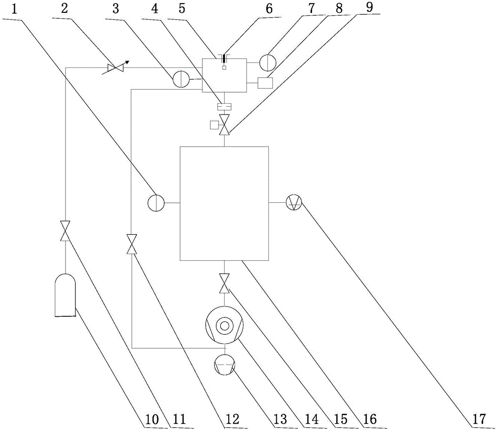
[0042] The present invention uses the structure of the static expansion method vacuum calibration device to perform dynamic calibration, but adopts a rapid expansion process. In order to achieve rapid expansion, replace the vacuum valve between the upstream chamber and the downstream chamber in the vacuum calibration device with an ultra-high vacuum gate valve, and determine whether to install and what conductance parameter is installed according to the response time of the calibrated vacuum gauge Components, thereby forming a dynamic vacuum calibration device to adapt to vacuum gauges with various response characteristics. Due to the complexity of the rapid expansion process, the present invention also needs to rebuild the standard pressure p std The calculation formula, using the pre-determined t-related conductance to calculate the standard pressure ch...


PUM


Abstract

The invention discloses a quick and dynamic vacuum calibration method for a vacuum gauge, which can realize quick and dynamic vacuum gauge calibration with an ms-grade response time. The quick and dynamic vacuum calibration method comprises the steps of replacing a vacuum valve between an upstream chamber and a downstream chamber in a vacuum calibration device in which a static expansion method by an ultrahigh vacuum gate valve; connecting a calibrated vacuum gauge with an upstream chamber; determining whether a current limiting component is mounted and the type of the flow guiding parameter of the current limiting component according to the response time of the calibrated vacuum gauge; after calibration is started, inflating standard gas into the upstream chamber until an initial pressure is reached; opening the ultrahigh vacuum gate valve for starting a quick gas expansion process and acquiring the displayed number of the calibrated vacuum gauge; and calculating a dynamic vacuum calibration standard pressure pstd according to a formula pstd=p10exp(-t / [tao]), drawing a dynamic vacuum calibration standard pressure curve in which the pstd changes along with time t, and filling the displayed number of the calibrated vacuum gauge for obtaining a calibration result.

Description

technical field [0001] The invention relates to the technical field of dynamic calibration of vacuum gauges, in particular to a fast dynamic vacuum calibration method. Background technique [0002] Vacuum calibration devices are used to provide standard pressures for vacuum gauges. At present, the response time of vacuum gauges used for rough and low vacuum range measurement has reached tens of milliseconds, while the standard pressure establishment time of commonly used static expansion method vacuum calibration devices is usually greater than 30s, which obviously cannot meet the dynamic calibration requirements of the above-mentioned vacuum gauges. [0003] The document "Dynamic vacuum measurement by an optical interferometric technique, 'Measurement Science and Technology' Volume 25, 2014, Pages 1-7", introduced the dynamic vacuum calibration device based on Michelson optical interferometer established by INRIM, Italy, This document proposes to invert the rapid change of...

Claims


Application Information

Patent Timeline
Patent Type & Authority Applications(China)
IPC IPC(8): G01L27/00
Inventor 习振华李得天赵澜孙雯君盛学民王永军马亚芳
Owner LANZHOU INST OF PHYSICS CHINESE ACADEMY OF SPACE TECH
Why Eureka
Try Eureka