Eureka AIR delivers breakthrough ideas for toughest innovation challenges, trusted by R&D personnel around the world.

Vortex line scanning thermal imaging detection system and method

A detection system and detection method technology, which is applied in the fields of equipment non-destructive testing, structural health monitoring and product quality control, can solve the problems of low detection accuracy, poor imaging effect, low detection efficiency, etc., and achieve high detection efficiency and low detection cost , good imaging effect

Inactive Publication Date: 2015-10-28
CHANGSHA UNIVERSITY
View PDF5 Cites 14 Cited by
  • Summary
  • Abstract
  • Description
  • Claims
  • Application Information

AI Technical Summary

Problems solved by technology

[0012] The existing eddy current thermal imaging detection system has low detection efficiency, poor imaging effect, low detection accuracy and high cost

Method used


Image

  • Vortex line scanning thermal imaging detection system and method
  • Vortex line scanning thermal imaging detection system and method
  • Vortex line scanning thermal imaging detection system and method

Examples


Embodiment Construction

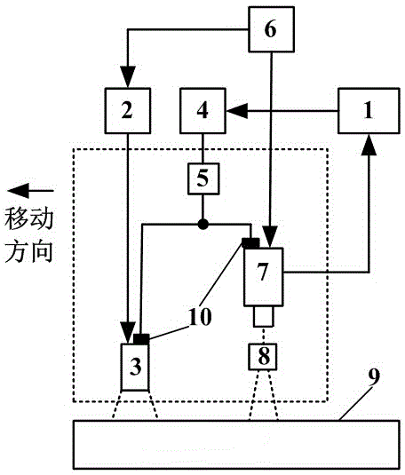
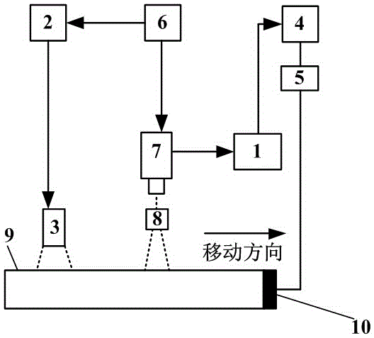
[0040] Such as figure 1 As shown, an embodiment of the detection system of the present invention includes a trigger 6 with two output ends, one output end of the trigger 6 is connected to the linear coil 3 through the eddy current heating module 2, and the other output of the trigger 6 End is connected with one-dimensional thermal imager 7, and described one-dimensional thermal imager 7 is configured in order to adjust the lens 8 of field of view size, and the output end of described one-dimensional thermal imager 7 is connected with computer 1, also includes computer 1 A scan control module 4 connected to the output end of the scan control module 4, the output end of the scan control module 4 is connected to the motion device 5, and the motion device 5 has a clamping device 10, and the clamping device 10 is respectively connected to the linear coil 3 and a The three-dimensional thermal imager 7 is fixedly connected, and the side of the linear coil 3 that performs linear heati...


PUM


Abstract

The invention discloses a vortex line scanning thermal imaging detection system and method. The detection system comprises a trigger with at least two output ends, one output end of the trigger is connected with a coil through a vortex flow heating module, other output ends of the trigger are respectively connected with one or more thermal imaging acquisition devices, each thermal imaging acquisition device is equipped with a lens used for adjusting the size of a viewing field, the output end of each thermal imaging acquisition device is connected with a computer, the vortex line scanning thermal imaging detection system further comprises a scanning control module connected with the output end of the computer, the output end of the scanning control module is connected with a motion device, a clamping device is further arranged on the motion device, the clamping device is respectively and fixedly connected with the coil and each thermal imaging acquisition device, or the clamping device is fixedly connected with a detected object. Compared with the prior art, the vortex line scanning thermal imaging detection system provided by the invention is convenient to use, high in detection efficiency, has a good imaging effect, high in defect detecting accuracy, low in detecting cost, and high in detecting result reliability.

Description

technical field [0001] The invention belongs to the fields of equipment nondestructive testing, structural health monitoring, product quality control, etc., and in particular relates to an eddy current line scanning thermal imaging detection system and method. Background technique [0002] With the development of modern science and industrial technology, non-destructive testing technology has become a necessary means to ensure product quality and equipment operation safety. The detection and quality control of large components is becoming a difficult point in the field of non-destructive testing. In order to ensure the reliability of detection, it is generally required that the detection system can run continuously, display images, and reduce costs as much as possible. [0003] At present, representative non-destructive testing technologies mainly include radiographic testing, ultrasonic testing, penetrant testing, magnetic particle testing, eddy current testing, and thermal...

Claims


Application Information

Patent Timeline
Patent Type & Authority Applications(China)
IPC IPC(8): G01N25/72
Inventor 杨瑞珍何赟泽
Owner CHANGSHA UNIVERSITY
Why Eureka
Eureka Blog
Learn More