End face coating fixture for stripe-geometry semiconductor laser and application thereof

A semiconductor and laser technology, applied in the field of bar-shaped semiconductor laser end-face coating fixtures, can solve the problems of bar warpage, difficult assembly, and rapid precision drop, reduce secondary or multiple damage, save processing material costs, prevent The effect of decreased flexibility

Inactive Publication Date: 2015-10-28
Shandong Huaguang Optoelectronics Co. Ltd.
8 Cites 17 Cited by

AI-Extracted Technical Summary

Problems solved by technology

[0012] 1. The design of the fixture structure is unreasonable. During the assembly process of the fixture to the coating furnace bracket, it is easy to cause the overall drop of the bar due to improper operation. However, the bar cannot be effectively clamped, causing the clamped bar to fall
[0013] 2. It is difficult to assemble the strips into the fixture. It is necessary to manually press the movable end of the fixture during operation, which requires high personnel skills, so the work efficiency is low, the success rate of strip loading is not high, and it is easy to cause product loss.
[0014] 3. The width or thickness of the bar end held by the fixture is fixed, and it cannot be adjusted accordingly for bars of different widths or thicknesses
Especially for the thickness of the bar, if the width of...

Abstract

The invention provides an end face coating fixture for a stripe-geometry semiconductor laser and an application thereof. The end face coating fixture comprises a bar strip coating fixture and an auxiliary strip assembly tool. The bar strip coating fixture comprises a sliding part and a combination frame. The combination frame comprises a u-shaped bottom frame and an upper cross frame. Columns at the two sides of the u-shaped bottom frame are internally and respectively provided with slide channels. The two ends of the sliding part are respectively provided with an inverted T-shaped embedded part. The slide channels are matched with the T-shaped embedded parts. The u-shaped bottom frame and the central part of the sliding part are provided with replaceable bar strip clamping ends. The invention also provides an auxiliary strip assembly tool. The auxiliary strip assembly tool is cooperatively used together with the bar strip coating fixture during the bar strip assembling process. The fixture is modular in design, novel in structure, simple to machine, convenient in assembly and high in nimbleness. For bar strips of different types, the fixture is good in adaptability, strong in practicality, easy to clean and maintain, and long in service life.

Application Domain

Laser detailsSemiconductor laser structural details

Technology Topic

Image

  • End face coating fixture for stripe-geometry semiconductor laser and application thereof
  • End face coating fixture for stripe-geometry semiconductor laser and application thereof
  • End face coating fixture for stripe-geometry semiconductor laser and application thereof

Examples

  • Experimental program(9)

Example Embodiment

[0055] Example 1,
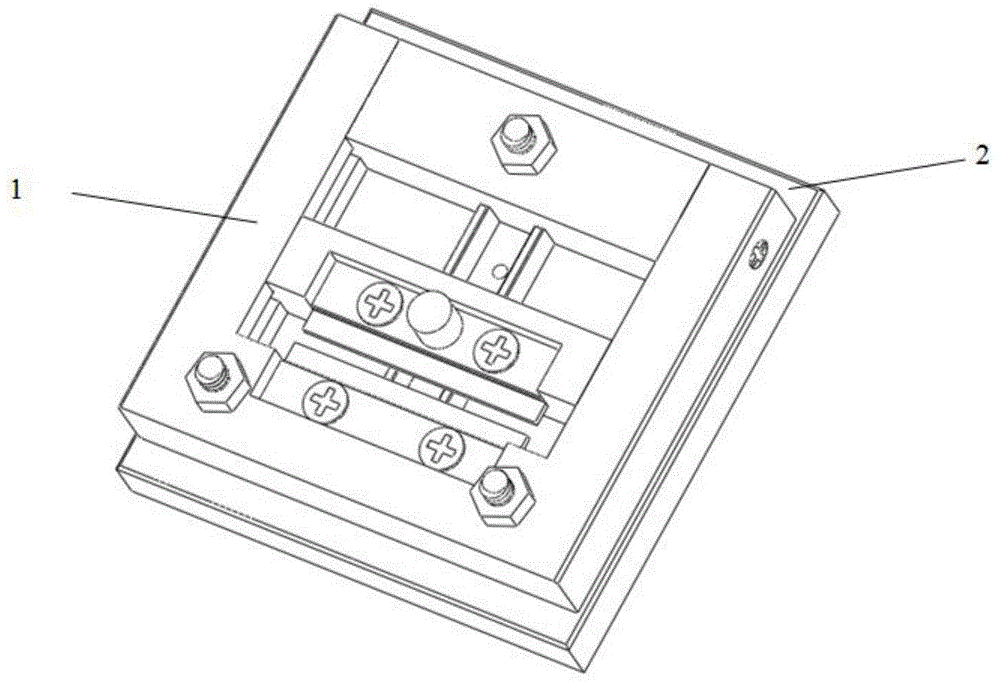
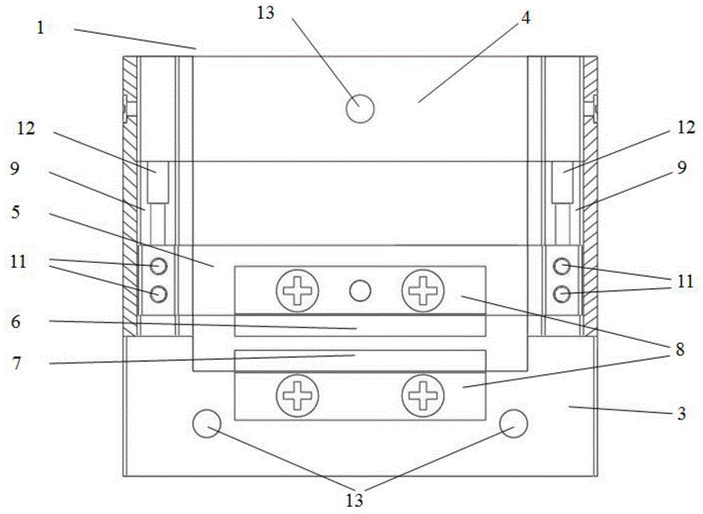
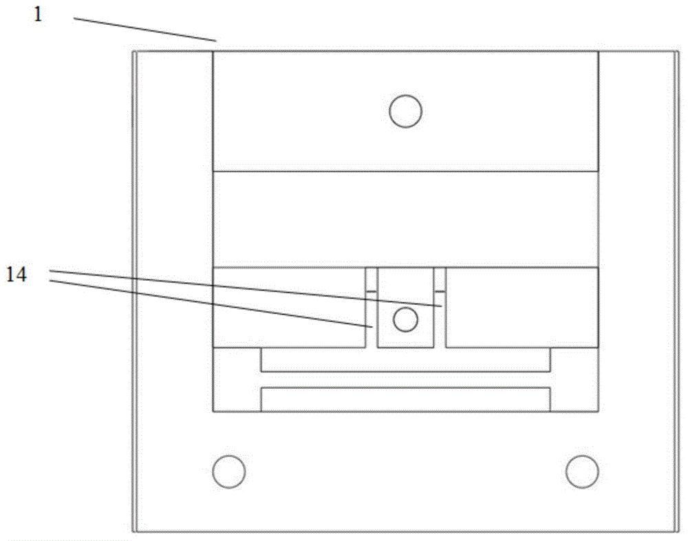
[0056] A strip-shaped semiconductor laser end surface coating fixture, comprising a bar coating fixture 1 and an auxiliary mounting tool 2. The bar coating fixture 1 includes a sliding part 5 and a combination frame, and the combination frame includes a U-shaped bottom frame 3 and an upper frame. The horizontal frame 4 is provided with slide rails 9 in the columns on both sides of the U-shaped bottom frame 3, and both ends of the slide portion 5 are embossed portions 10 respectively. The embedded part 10 is matched.
[0057] A detachable upper bar clamping end 6 is installed on the sliding part 5, and a detachable chin bar clamping end 7 is installed on the bottom of the U-shaped bottom frame 3. The upper bar clamping The end 6 and the chin bar clamping end 7 are arranged oppositely. The upper bar gripping end 6 is fixed on the central recess of the sliding part 5 by spacers and bolts; the chin bar gripping end 7 is fixed on the bottom of the U-shaped bottom frame 3 by spacers and bolts On the central concave platform. The auxiliary strip mounting tool is used in cooperation with the strip coating fixture in the process of assembling the strip.

Example Embodiment

[0058] Example 2,
[0059] A strip-shaped semiconductor laser end surface coating fixture as described in embodiment 1, the difference is that the sliding portion 5 is connected to the auxiliary mounting tool 2 through a limiting component.

Example Embodiment

[0060] Example 3.
[0061] A strip-shaped semiconductor laser end surface coating fixture as described in embodiment 1, the difference is that the combined frame is rectangular as a whole, and the upper horizontal frame 4 is embedded and arranged at the open end of the U-shaped bottom frame 3.

PUM

no PUM

Description & Claims & Application Information

We can also present the details of the Description, Claims and Application information to help users get a comprehensive understanding of the technical details of the patent, such as background art, summary of invention, brief description of drawings, description of embodiments, and other original content. On the other hand, users can also determine the specific scope of protection of the technology through the list of claims; as well as understand the changes in the life cycle of the technology with the presentation of the patent timeline. Login to view more.

Similar technology patents

Classification and recommendation of technical efficacy words

  • Novel structure
  • Practical

Digital controlled temp. regulating automatic water tap

InactiveCN101000111ANovel structureRealize the automation of water temperature adjustmentOperating means/releasing devices for valvesMultiple way valvesAutomatic faucetElectricity
Owner:宁波意耐特阀门有限公司
Why Eureka
Try Eureka