Drill jig structure for drilling plate-shaped metal component

A technology of metal parts and jigs, which is applied in the field of jig structures, can solve problems such as high cost and complicated procedures, and achieve the effects of improving production efficiency, simple structure, and reducing labor intensity

Inactive Publication Date: 2015-11-04
HARBIN
View PDF5 Cites 2 Cited by
  • Summary
  • Abstract
  • Description
  • Claims
  • Application Information

AI Technical Summary

Problems solved by technology

[0003] The technical problem to be solved by the present invention: the problem of c

Method used


Image

  • Drill jig structure for drilling plate-shaped metal component
  • Drill jig structure for drilling plate-shaped metal component
  • Drill jig structure for drilling plate-shaped metal component

Examples


Embodiment Construction

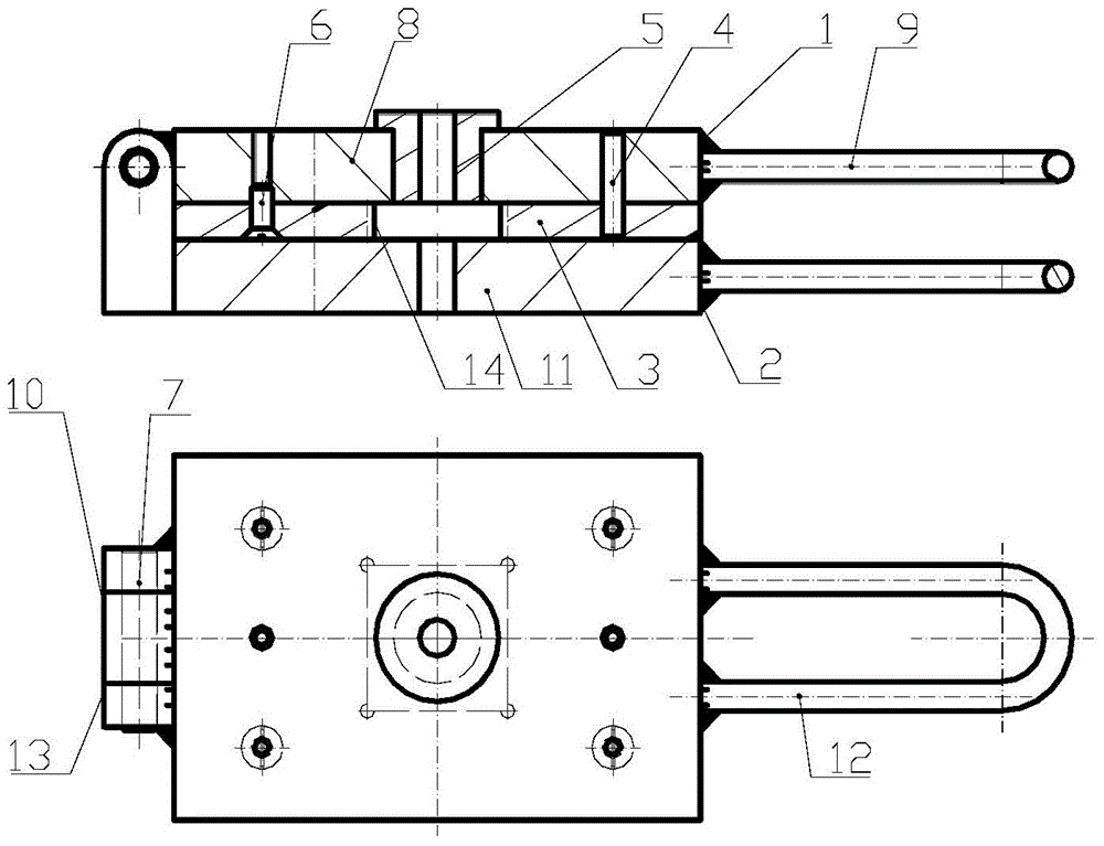
[0011] The installation and working methods of the present invention will be described below in conjunction with the accompanying drawings.

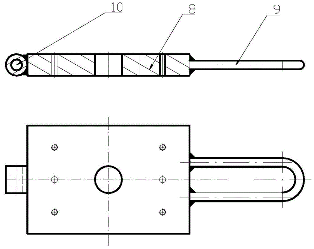
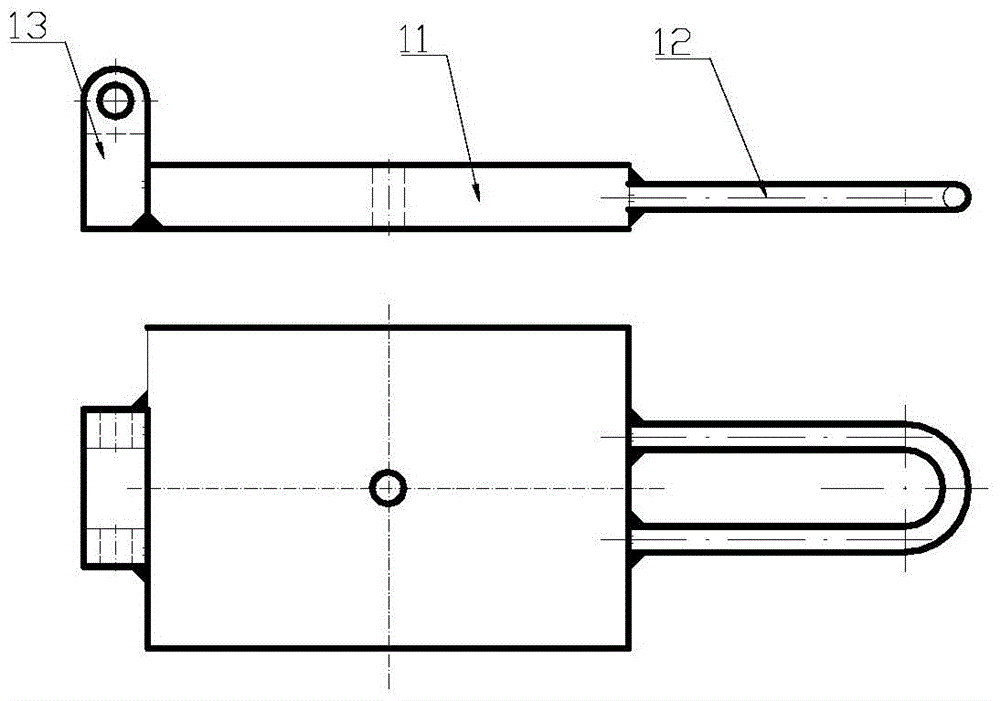
[0012] Such as figure 1 Assemble the template as shown, template assembly 1 (see figure 2 ) is welded by drill plate 8, handle 9, steel sleeve 10. Base plate assembly 2 (see image 3 ) is welded by the base plate 11, the handle 12 and the support 13, the drill formwork assembly 1 is connected with the positioning plate through the pin a4 and the screw 6, and then forms a hinge connection with the base plate assembly 2 through the pin 7.

[0013] When working, open the drilling mold through the handle, first put the bottom plate assembly 2 on the top, and the drilling template assembly 1 below, place the parts in the positioning groove 14 of the positioning plate 4 to close the mold, then turn over to make the drilling template assembly 1 upward, and then place On the drilling machine, it can be drilled through the drill sleeve, or it...


PUM


Abstract

The invention relates to a drill jig structure for drilling a plate-shaped metal component. The drill jig structure comprises a drill jig plate assembly 1, a bottom plate assembly 2, a positioning plate 3, a pin a 4, a drill sleeve 5, a screw 6 and a pin b 7. The special drill jig structure is designed, the structure is simple, and the requirement for machining precision of a plate-shaped metal component hole is met. The requirements of various machine types in a plate-shaped metal component workshop are met, the labor intensity of workers is relieved, and the production efficiency is improved.

Description

technical field [0001] The invention relates to a drilling mold structure for drilling plate metal parts, which belongs to the field of plate forming. Background technique [0002] The existing method for making the holes of plate-shaped metal parts is that most of the parts with a large number and different hole sizes are marked and then drilled, which is difficult to meet the accuracy requirements; for the small number of holes, punching dies are used. Punching out, the structure of the mold is complicated, the cost of manufacturing and maintenance is high, and it is difficult to meet the demand. The above method of hole making has certain limitations. For plate-shaped metal parts with a large number of holes and different hole sizes, using the above-mentioned technology requires cumbersome operations for workers, long manufacturing cycles, and poor interchangeability of parts. If the number of holes is small, a punching die is used, but the cost of the punching die is r...

Claims


Application Information

Patent Timeline
IPC IPC(8): B23B47/28
Inventor 崔丽娟赵红卫孙士海
Owner HARBIN
Why Eureka
Try Eureka