Adjustable multi-shaft automatic screwing machine and position adjustment method thereof

A technology of automatic screw locking machine and screw locking mechanism, which is applied in metal processing, metal processing equipment, manufacturing tools, etc., can solve the problems of low efficiency, inability to move relatively, and inapplicability, and achieves simple and convenient operation process, stable and reliable work. , the effect of easy adjustment

Active Publication Date: 2015-11-04
XIAMEN UNIV OF TECH
View PDF18 Cites 18 Cited by
  • Summary
  • Abstract
  • Description
  • Claims
  • Application Information

AI Technical Summary

Problems solved by technology

[0002] Due to the large size and model of flat-panel TVs and the large area of ​​the back panel, the screws that need to be locked are short in length, large in diameter and large in number, and are arranged in a matrix. At present, in the production process, the locking of the screws is mainly done manually. Completion, low efficiency, poor stability
Existing adjustable screw locking machines often only have a single locking screw mechanism, and for multiple locking screw mechanisms, the distance between the electric screwdrivers is often not adjustable, and the flexibility is poor
For some equipment that can adjust the distance between electric batches, it is often mechanically adjusted, with a low degree of automation and long adjustment time
[0003] For example: Chinese patent application number 201010212967.8 discloses a kind of "automatic locking screw machine" and the application number is 201020670310.1, and the name is called "multifunctional automatic screw machine". The workpiece is screw-locked, but it is not suitable for products that need to lock a large number of screws like flat-screen TVs
[0004] Another example: the Chinese invention patent application with the application number 201510180295.X and the name "a multi-axis multi-station independent automatic locking screw machine" has an assembly line and multiple processing mechanisms arranged beside the assembly line, which can realize the Different positions or even different surfaces of the product are used for screw locking, but it is also impossible to perform screw locking for different positions of a product at a time
[0005] In the above-mentioned prior patent, the relative distance between each axis, that is, the screw attachment units, cannot be adjusted, so the product can only be adapted to the machine. For products such as flat-panel TVs, due to the large number of locking screws and the size and model of each product Each is different, only a single screw can be locked one by one, the efficiency is very low
[0006] CN201220743487.9 discloses an "automatic locking screw machine for mobile phone assembly". Although the two electric screwdrivers of the locking screw machine can move relative to each other, the movement is for the movement before different stations, and two electric screwdrivers are set. The purpose of the screwdriver is only to improve efficiency, and each operation can only lock one screw position of the product
CN201310726959.9 discloses "a gantry-type automatic locking screw mechanism". Although a plurality of automatic locking screw modules set by it can move in three-dimensional space, the multiple automatic locking screw modules arranged on the gantry cannot move. Relative movement can only be moved at the same time. If you want to adjust the distance between the two automatic locking screw modules, you can only stop the operation. The degree of automation is low and the adjustment time is long

Method used


Image

  • Adjustable multi-shaft automatic screwing machine and position adjustment method thereof
  • Adjustable multi-shaft automatic screwing machine and position adjustment method thereof
  • Adjustable multi-shaft automatic screwing machine and position adjustment method thereof

Examples


Embodiment Construction

[0031] The present invention will be further described in detail below in conjunction with the accompanying drawings and specific embodiments.

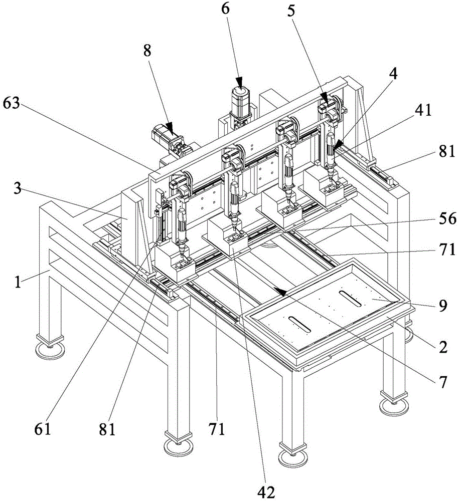
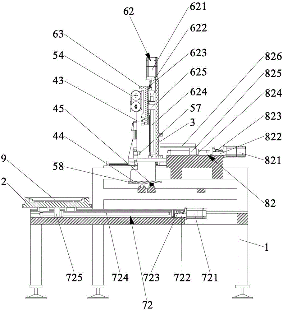
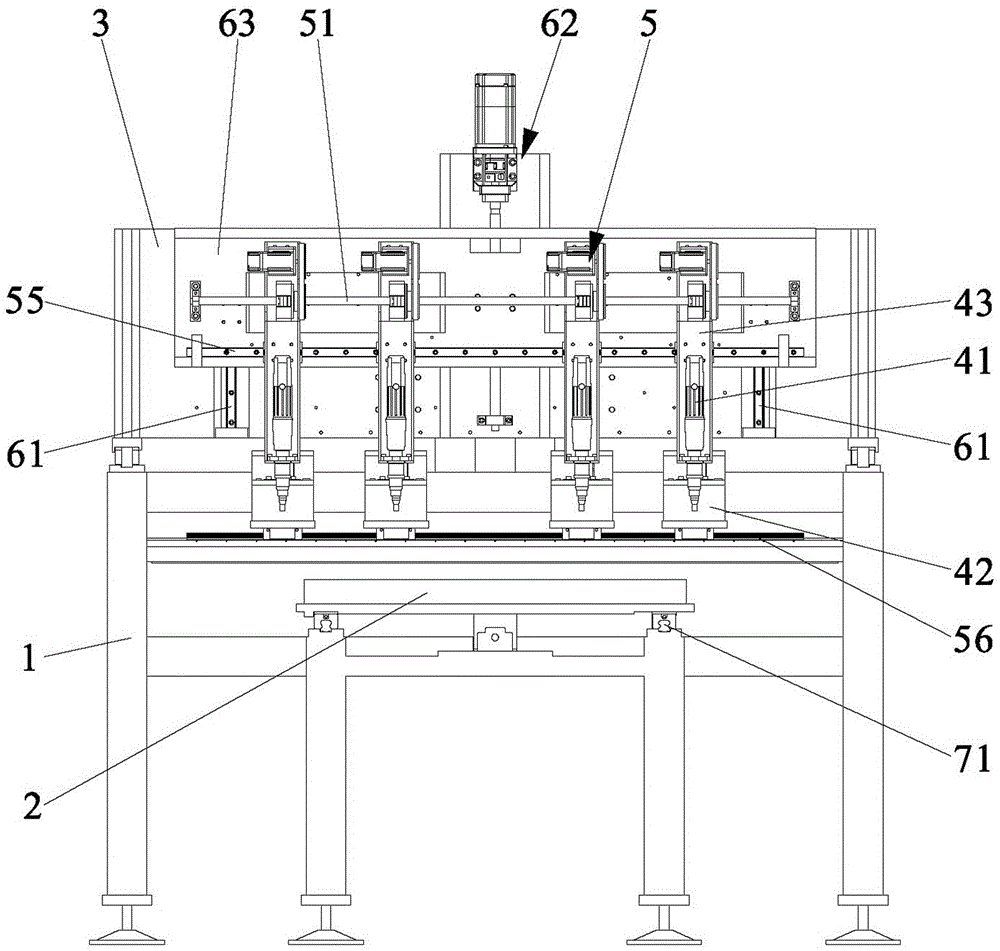
[0032] What the present invention discloses is an adjustable multi-axis automatic locking screw machine, such as Figure 1 to Figure 5 Shown is a preferred embodiment of the present invention. The automatic screw machine includes a frame 1, a storage platform 2, a gantry frame 3, a plurality of locking screw mechanisms 4, an adjustable locking screw mechanism 4 moving on the X axis, a position adjustment mechanism 5, and a driving locking screw mechanism 4 up and down. A moving Z-axis motion mechanism 6, a Y-axis motion mechanism and a control mechanism that can drive the storage platform 2 or the locking screw mechanism 4 to move. in:

[0033] The storage table 2 is used for fixedly installing workpieces to be processed, and it is arranged on the frame 1 . The gantry frame 3 is also arranged on the frame 1 and spans above the stor...


PUM


Abstract

The invention discloses an adjustable multi-shaft automatic screwing machine and a position adjustment method thereof. The screwing machine comprises a machine frame, an object containing table, a portal frame, a plurality of screwing mechanisms, a position adjustment mechanism capable of adjusting movement of the screwing mechanisms in the X axis direction, a Z-axis movement mechanism capable of driving the screwing mechanisms to vertically move, a Y-axis movement mechanism capable of driving the object containing table or the screwing mechanisms to move and a control mechanism. The position adjustment mechanism comprises a nut-rotating-type lead screw pair fixed to the portal frame. A plurality of nuts are arranged on the nut-rotating-type lead screw pair according to the number of the screwing mechanisms. Each nut is provided with an X-axis nut base which is fixedly linked with the corresponding screwing mechanism. Each screwing mechanism is provided with an X-axis motor to be connected with the corresponding nut in a transmission manner through a transmission mechanism. According to the adjustable multi-shaft automatic screwing machine and the position adjustment method, the relative positions among the screwing mechanisms can be adjusted to adapt to screw hole positions in a to-be-screwed workpiece, and therefore the multiple screw hole positions in a row in the workpiece can be screwed at the same time.

Description

technical field [0001] The invention relates to the field of screw locking equipment, in particular to an adjustable multi-axis automatic screw locking machine and a position adjustment method thereof. Background technique [0002] Due to the large size and model of flat-panel TVs and the large area of ​​the back panel, the screws that need to be locked are short in length, large in diameter and large in number, and are arranged in a matrix. At present, in the production process, the locking of the screws is mainly done manually. Completion, low efficiency and poor stability. Existing adjustable screw locking machines often only have a single locking screw mechanism, and for multiple locking screw mechanisms, the distance between the electric screwdrivers is often not adjustable, and the flexibility is poor. For some equipment that can adjust the distance between electric batches, it is often a mechanical adjustment, with a low degree of automation and a long adjustment tim...

Claims


Application Information

Patent Timeline
Patent Type & Authority Applications(China)
IPC IPC(8): B23P19/06
CPCB23P19/069
Inventor 刘建春汤辉煌杜欣宇柯晓龙黄海滨林晓辉
Owner XIAMEN UNIV OF TECH
Why Eureka
Try Eureka