Check patentability & draft patents in minutes with Patsnap Eureka AI!

Cyclical shot blasting machine for electric tricycle frame

A technology of shot blasting machine and electric tricycle, which is applied to the processing device of used abrasives, abrasive jetting machine tools, abrasives, etc. It can solve the problems of affecting shot blasting effect and working environment, poor surface process state, high production cost, etc. , to achieve the effect of saving human resources and enterprise production costs, deteriorating the environment and safe operation, and improving the effect of shot blasting

Inactive Publication Date: 2015-11-04
JIANGSU JIUCHANG MACHINERY CO LTD
View PDF0 Cites 0 Cited by
  • Summary
  • Abstract
  • Description
  • Claims
  • Application Information

AI Technical Summary

Problems solved by technology

[0002] The electric tricycle frame itself has poor fatigue resistance after molding, serious stress concentration, poor surface technology, burrs, oxide scales, and rust layers. It needs to be processed by a shot blasting machine. The existing shot blasting The cleaning machine cleans the frame of the electric tricycle in a straight line and single time, which is prone to cleaning dead angles and the cleaning effect is not good. The input and output ends of the shot blasting cleaning machine are not at the same end and two people are required to operate. A lot of human resources are needed, and the production cost of the enterprise is high. At the same time, there is no air inlet on the top of the existing shot blasting machine, and there will be a lot of dust on the workpiece, which is not clean enough, which will affect the shot blasting effect and the working environment.

Method used


Image

  • Cyclical shot blasting machine for electric tricycle frame
  • Cyclical shot blasting machine for electric tricycle frame
  • Cyclical shot blasting machine for electric tricycle frame

Examples


Embodiment Construction

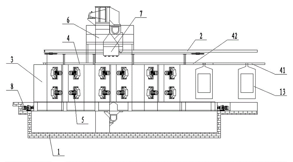
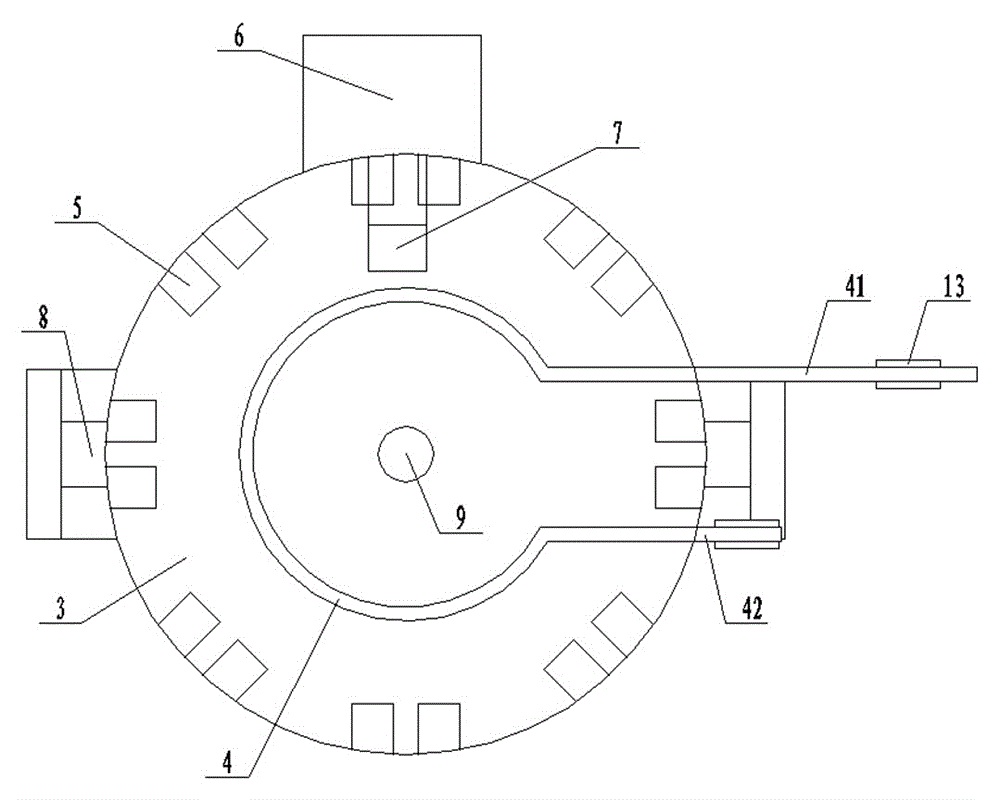
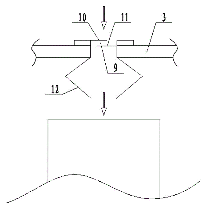
[0011] The specific content of the present invention will be described in detail below in conjunction with the accompanying drawings and specific embodiments.

[0012] Such as figure 1 , figure 2 , image 3 As shown, the circular shot blasting machine for the frame of an electric tricycle includes: a frame 1, the frame 1 is supported on the ground 2, a cylindrical cleaning chamber 3 is arranged on the frame 1, and a cylindrical cleaning chamber 3 is arranged on the frame 1. The inner upper end of the cylindrical cleaning chamber 3 is provided with a circular circulation conveying track 4, on which an input end 41 and an output end 42 are arranged, and on the inner wall of the cylindrical cleaning chamber 3, several The shot blaster 5 is provided with a hoist 6 on the frame 1 on the side of the cleaning chamber 3, and the upper end of the hoist 6 is connected with the separator 7 arranged on the upper end of the frame 1, and the hoist 6 The lower end of the lower end is con...


PUM


Abstract

The invention discloses a cyclical shot blasting machine for an electric tricycle frame. The cyclical shot blasting machine comprises a machine frame. The machine frame is supported on the ground. A cylindrical cleaning room is arranged on the machine frame. A circular circulating conveying rail is arranged at the upper end inside the cylindrical cleaning room. An input end and an output end are arranged on the circular loop conveying rail. A plurality of shot blasting devices are evenly arranged on the inner wall of the cylindrical cleaning room. A lifting machine is arranged on the portion, on one side of the cleaning room, of the machine frame. The upper end of the lifting machine is connected with a separator arranged at the upper end of the machine frame. The lower end of the lifting machine is connected with a spiral conveyor arranged at the lower end of the machine frame. The upper end of the cylindrical cleaning room is provided with an air inlet structure. The air inlet structure comprises an air inlet, an upper baffle, a lower baffle and L-shaped protective plates, wherein the air inlet is formed in the upper end of the cylindrical cleaning room, the upper baffle and the lower baffle are arranged in the air inlet, and the L-shaped protective plates are symmetrically arranged on the portions, on the two sides of the lower end of the air inlet, of the cleaning room.

Description

technical field [0001] The invention relates to a shot blasting machine, in particular to a cycle shot blasting cleaning machine for an electric tricycle frame. Background technique [0002] The electric tricycle frame itself has poor fatigue resistance after molding, serious stress concentration, poor surface technology, burrs, oxide scales, and rust layers. It needs to be processed by a shot blasting machine. The existing shot blasting The cleaning machine cleans the frame of the electric tricycle in a straight line and single time, which is prone to cleaning dead angles and the cleaning effect is not good. The input and output ends of the shot blasting cleaning machine are not at the same end and two people are required to operate. A lot of human resources are needed, and the production cost of the enterprise is high. At the same time, there is no air inlet on the top of the existing shot blasting machine, and there will be a lot of dust on the workpiece, which is not...

Claims


Application Information

Patent Timeline
IPC IPC(8): B24C3/18B24C9/00
Inventor 陈九昌
Owner JIANGSU JIUCHANG MACHINERY CO LTD
Features
  • R&D
  • Intellectual Property
  • Life Sciences
  • Materials
  • Tech Scout
  • Unparalleled Data Quality
  • Higher Quality Content
  • 60% Fewer Hallucinations
Learn More