
Air source enhanced vapor injection heat pump system

A technology of jet enthalpy increase and heat pump system, which is applied in heat recovery system, climate sustainability, energy-saving heating/cooling, etc., can solve the problem of difficulty in realizing both heating and cooling, large compression ratio of heat pump, and frosting efficiency of evaporator. Operation and other problems to achieve the effect of reducing irreversibility, reducing compression ratio, and avoiding energy backflow

Inactive Publication Date: 2015-11-04
TIANJIN UNIV
View PDF8 Cites 16 Cited by
  • Summary
  • Abstract
  • Description
  • Claims
  • Application Information

AI Technical Summary

Problems solved by technology

[0005] The invention provides a high-efficiency dual-purpose air source air injection enthalpy-increasing heat pump system for cooling and heating, which solves the technical problems of the existing heat pumps such as large compression ratio, difficulty in realizing dual-purpose heating and cooling, and frosting of the evaporator and low efficiency operation. In the system, the air jet enthalpy-increasing compressor is used, and the refrigerant subcooling heat exchanger is used to heat the air passing through the outdoor evaporator to achieve the winter defrosting effect, and through the cooperation of multiple four-way valves, both winter and summer are realized. It can effectively improve the efficiency and operation safety of the entire heat pump system by using energy-saving means such as air supply in the middle of the compressor and internal heat exchange.

Method used


Image

  • Air source enhanced vapor injection heat pump system
  • Air source enhanced vapor injection heat pump system
  • Air source enhanced vapor injection heat pump system

Examples


Embodiment Construction

[0024] The present invention will be described in further detail below through specific examples. The following examples can enable those skilled in the art to understand the present invention more comprehensively, but do not limit the present invention in any way.

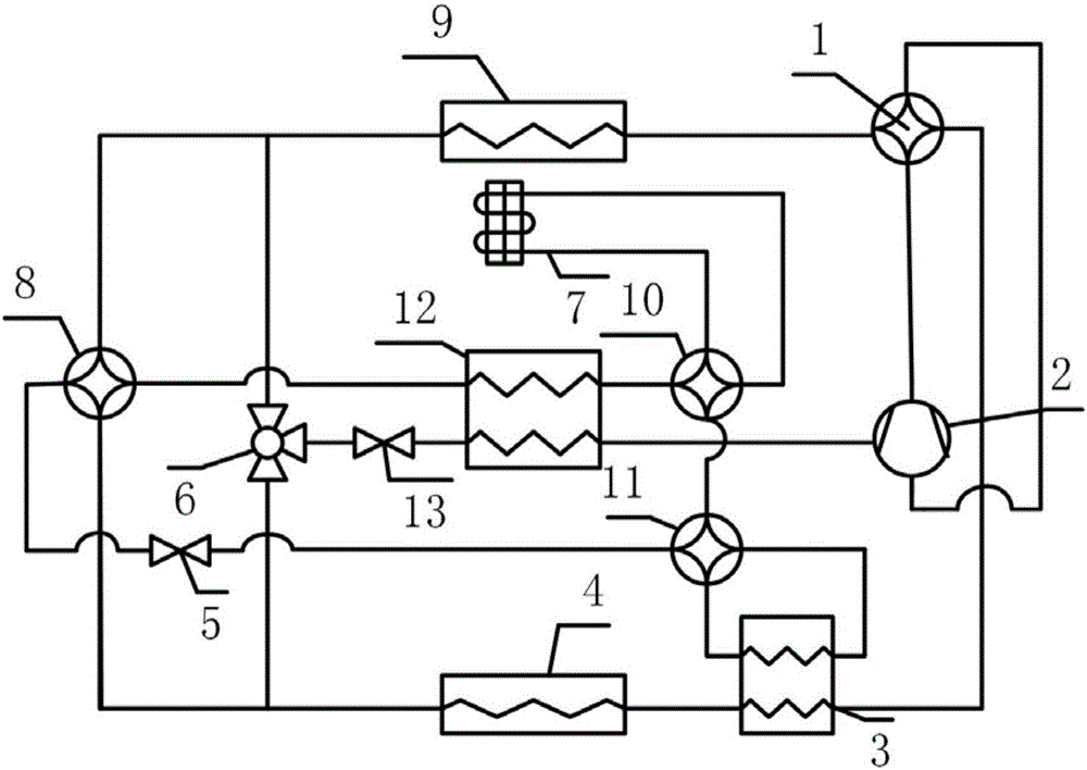
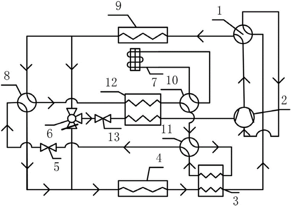
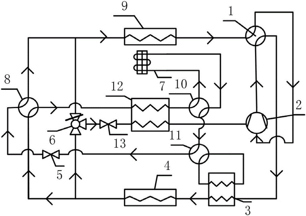
[0025] Such as figure 1 As shown, this embodiment discloses a high-efficiency dual-purpose air source air jet enthalpy-increasing heat pump system for cooling and heating, which consists of a first four-way reversing valve 1, a second four-way reversing valve 8, and a third four-way reversing valve Valve 10, fourth four-way reversing valve 11, air injection enthalpy increasing compressor 2, regenerator 3, economizer 12, first refrigerant air-cooled heat exchanger 9, second refrigerant air-cooled heat exchanger 4. The first electronic expansion valve 5, the second electronic expansion valve 13, the three-way valve 6, and the refrigerant subcooling heat exchanger 7; in this system, the first refrigerant air-cooled h...


PUM

PropertyMeasurementUnit
Hydraulic diameteraaaaaaaaaa

Abstract

The invention relates to an efficient air source heat pump system, in particular to an air source enhanced vapor injection heat pump system which comprises a first four-way reversing valve, an enhanced vapor injection compressor, a heat regenerator, a first refrigerant air-cooling type heat exchanger, a first electronic expansion valve, a three-way valve, a refrigerant supercooling heat exchanger, a second four-way reversing valve, a second refrigerant air-cooling type heat exchanger, a third four-way reversing valve, a fourth four-way reversing valve, an economizer and a second electronic expansion valve. By means of the air source enhanced vapor injection heat pump system, the technical problems that the compression ratio of an existing heat pump is large, the dual purposes of heating and refrigerating are difficult to achieve at the same time, an evaporator is frosted, and operation efficiency is low are solved. By using the enhanced vapor injection compressor in the system and heating air passing through the outdoor evaporator through the refrigerant supercooling heat exchanger, the defrosting effect is achieved in winter. Moreover, through cooperation of the multiple four-way valves, the energy-saving means of center gas supplementation and inner heat exchange of the compressor can be utilized in winter and summer, and the efficiency and operation safety of the whole heat pump system are effectively improved.

Description

technical field [0001] The invention relates to a heating and refrigeration cycle system, more specifically, to a high-efficiency air source heat pump system. Background technique [0002] As a kind of energy-saving device, heat pump has been paid more and more attention, and is considered as an effective means of energy-saving and emission-reduction. Heat pump systems are widely used because they can provide cooling in summer and heat in winter and are easy to operate. However, in regions with hot summer and cold winter, air source heat pumps cannot be widely used due to the low outdoor temperature in winter, large compression ratio and frosting. Therefore, it is necessary to develop high-efficiency heat pump units that can be used in hot summer and cold winter regions. [0003] At present, the gas-injection enthalpy-increasing compressor adopts two-stage throttling intermediate air-injection technology, and uses a flash evaporator for gas-liquid separation to achieve the ...

Claims


Application Information

Patent Timeline
IPC IPC(8): F25B13/00F25B41/04F25B41/20F25B41/34
CPCY02B30/52
Inventor 李敏霞吕岩李双俊
Owner TIANJIN UNIV
Learn More