Anti-reflective electrically-driven 3D liquid crystal lens

A liquid crystal lens and electric drive technology, applied in optics, instruments, nonlinear optics, etc., can solve problems such as interference with the user's viewing of the screen, high reflectivity of the 3D display, and reduced screen contrast

Inactive Publication Date: 2015-11-04
SHANTOU GOWORLD DISPLAY (PLANT II) CO LTD
View PDF5 Cites 5 Cited by
  • Summary
  • Abstract
  • Description
  • Claims
  • Application Information

AI Technical Summary

Problems solved by technology

[0003] This liquid crystal lens, due to the large refractive index difference between the first electrode and the second electrode of the indium tin oxide film, the first substrate, the second substrate, the first alignment layer, and the second alignment layer, It will lead to obvious film reflection on the 3D liquid crystal lens, which will cause th...

Method used


Image

  • Anti-reflective electrically-driven 3D liquid crystal lens
  • Anti-reflective electrically-driven 3D liquid crystal lens

Examples


Embodiment 1

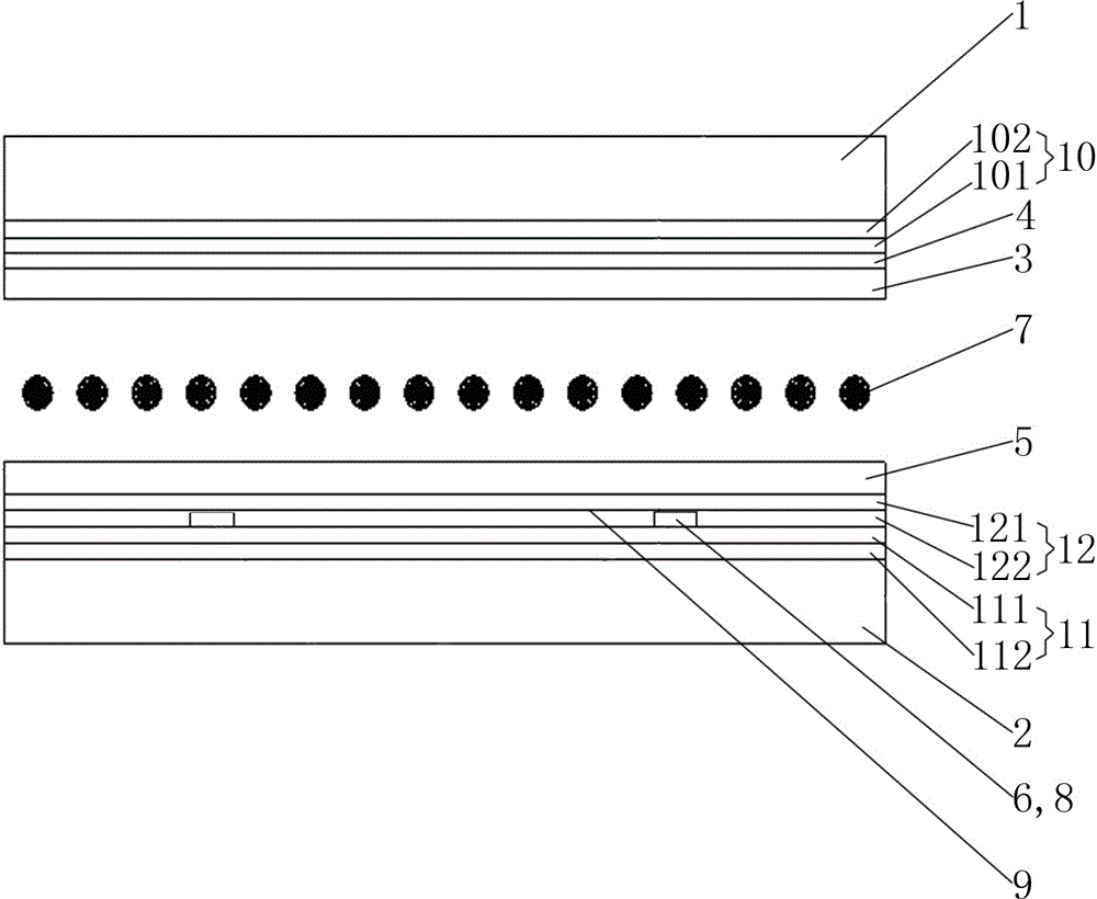
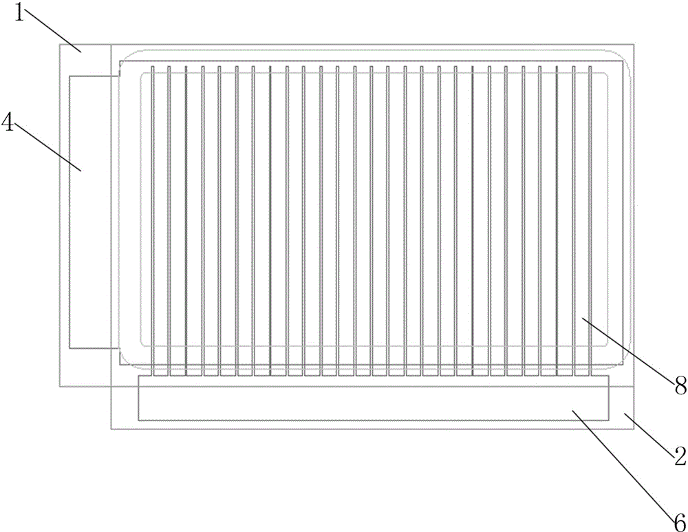
[0022] Such as figure 1 and figure 2 As shown, this anti-reflection electrically driven 3D liquid crystal lens includes a first substrate 1, a second substrate 2, a first alignment layer 3 and a first electrode 4 disposed inside the first substrate 1, and a first electrode 4 disposed inside the second substrate 2. The second alignment layer 5 and the second electrode 6; a liquid crystal layer 7 is arranged between the first substrate 1 and the second substrate 2, and the liquid crystal layer 7 is a nematic liquid crystal; the first electrode 4 and the second electrode 6 are oxide Indium tin film, the first electrode 4 is a continuous electrode on the whole surface, the second electrode 6 is composed of a plurality of linear electrodes 8 arranged side by side, and a gap 9 is provided between two adjacent linear electrodes 8; the first electrode 4 and the second electrode A first anti-reflection layer 10 is provided between the substrates 1. The first anti-reflection layer 10 ...

Embodiment 2

[0028] In the case that other parts are the same as in the first embodiment, the difference is that the first sublayer 101 is a titanium oxide film, and the second sublayer 102 is a silicon oxide film.

Embodiment 3

[0030] When other parts are the same as those in the first or second embodiment, the difference is that the first sublayer 101 is close to the first electrode 4 , and the second sublayer 102 is close to the first substrate 1 .


PUM


Abstract

The invention relates to an anti-reflective electrically-driven 3D liquid crystal lens. The anti-reflective electrically-driven 3D liquid crystal lens comprises a first substrate, a second substrate, a first alignment layer, a first electrode, a second alignment layer and a second electrode, wherein the first alignment layer and the first electrode are arranged on the inner side of the first substrate, and the second alignment layer and the second electrode are arranged on the inner side of the second substrate. A liquid crystal layer is arranged between the first substrate and the second substrate. The first electrode is a whole-face continuous electrode, and the second electrode is composed of a plurality of side-by-side linear electrodes. A first anti-reflective layer is arranged between the first electrode and the first substrate and is a transparent insulating film layer. The overall refractive rate of the first anti-reflective layer is larger than the refractive rate of the first substrate and smaller than the refractive rate of the first electrode. By arranging the first anti-reflective layer between the first electrode and the first substrate, reflection of the film layer between the first electrode and the first substrate is reduced, and therefore the reflective rate of the 3D liquid crystal lens is greatly decreased, and an image displayed under the bright environment is made to have high contrast.

Description

technical field [0001] The invention relates to a display device, in particular to an anti-reflection electrically driven 3D liquid crystal lens. Background technique [0002] Naked-eye 3D displays generally require a 3D liquid crystal lens to be placed in front of a flat-panel display. The second alignment layer and the second electrode are formed inside the second substrate, a liquid crystal layer is arranged between the first substrate and the second substrate, and the first electrode and the second electrode are both indium tin oxide (ITO) thin films, wherein , the first electrode is a continuous electrode on the entire surface, and the second electrode is composed of a plurality of line electrodes arranged side by side. [0003] This liquid crystal lens, due to the large refractive index difference between the first electrode and the second electrode of the indium tin oxide film, the first substrate, the second substrate, the first alignment layer, and the second align...

Claims


Application Information

Patent Timeline
IPC IPC(8): G02F1/29G02B27/22G02B1/11
CPCG02B1/115G02B30/27G02F1/29
Inventor 吴永俊沈奕林钢詹前贤陈绍源吕岳敏张汉焱纪伟丰苏赞加
Owner SHANTOU GOWORLD DISPLAY (PLANT II) CO LTD
Why Eureka
Try Eureka