
Planar rectification diode

A rectifier diode, planar technology, used in electrical components, electrical solid devices, circuits, etc., can solve problems such as easy insertion of pins too deep, unstable welding, and impact on the service life of diodes.

Inactive Publication Date: 2015-11-04
NANTONG MINICHIP MICRO ELECTRONICS
View PDF5 Cites 2 Cited by
  • Summary
  • Abstract
  • Description
  • Claims
  • Application Information

AI Technical Summary

Problems solved by technology

[0004] 1) Pins are easily bent or broken;
[0005]2) The pins are easily inserted too deep when inlaying, resulting in unstable welding
[0006] These shortcomings have seriously affected the service life of the diode

Method used


Image

  • Planar rectification diode

Examples


Embodiment Construction

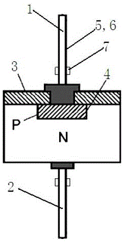
[0016] Such as figure 1 As shown, the planar rectifier diode of the present invention includes an anode lead (1), a cathode lead (2), a silicon dioxide protective layer (3) and a PN junction (4), and the anode lead (1) is connected to the The silicon protective layer (3) is connected, the silicon dioxide protective layer (3) is connected to the PN junction (4), and the outside of the anode lead (1) and the cathode lead (2) are sequentially covered with an adhesive layer ( 5) and copper-nickel alloy layer (6). A positioning block (7) is arranged on the anode lead wire (1) and the cathode lead wire (2).


PUM


Abstract

The invention provides a planar rectification diode. The planar rectification diode comprises an anode leading wire (1), a cathode leading wire (2), a silicon dioxide protective layer (3) and a positive-negative (PN) junction (4), wherein the anode leading wire (1) is connected with the silicon dioxide protective layer (3), the silicon dioxide protective layer (3) is connected with the PN junction (4), and an adhesive layer (5) and a copper-nickel alloy layer (6) are sequentially coated outside the anode leading wire (1) and the cathode leading wire (2). The planar rectification diode provided by the invention has the following technical effects: 1) a pin is difficult to be bent or broken; and 2) the pin is difficult to be inserted deeply during embedment, and welding instability is prevented.

Description

technical field [0001] The invention relates to a planar rectifier diode and belongs to the technical field of semiconductors. Background technique [0002] Diode is one of the most commonly used electronic components. Its biggest characteristic is unidirectional conduction, that is, current can only flow from one direction of the diode. The function of the diode is a rectifier circuit, a detection circuit, a voltage stabilization circuit, and various modulation circuits. , are mainly composed of diodes, and their principles are very simple. It is precisely because of the invention of diodes and other components that we have the birth of our colorful electronic information world. [0003] The existing diodes have the following disadvantages: [0004] 1) The pins are easily bent or broken; [0005] 2) The pins are easy to be inserted too deep when inlaying, resulting in unstable welding. [0006] These shortcomings have seriously affected the service life of the diode...

Claims


Application Information

Patent Timeline
Patent Type & Authority Applications(China)
IPC IPC(8): H01L29/861H01L23/48
CPCH01L24/01H01L23/48H01L29/861H01L29/8611
Inventor 周明
Owner NANTONG MINICHIP MICRO ELECTRONICS
Learn More