Deflection voltage electric composite materials

A flexural voltage-electric, composite material technology, applied in circuits, piezoelectric/electrostrictive/magnetostrictive devices, electrical components, etc., can solve the problems of reduced material bearing capacity and narrowed use range

Active Publication Date: 2015-11-04
UNIV OF SCI & TECH OF CHINA
View PDF4 Cites 13 Cited by
  • Summary
  • Abstract
  • Description
  • Claims
  • Application Information

AI Technical Summary

Problems solved by technology

The requirement of this material is that the length of the strip is much greater than the width and thickness of the material, resulting in a reduction in the use range of the material and a reduction in the load-bearing capacity of the material.

Method used


Image

  • Deflection voltage electric composite materials
  • Deflection voltage electric composite materials
  • Deflection voltage electric composite materials

Examples


Embodiment 1

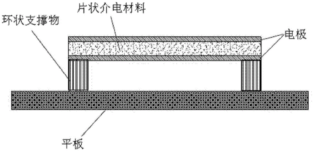
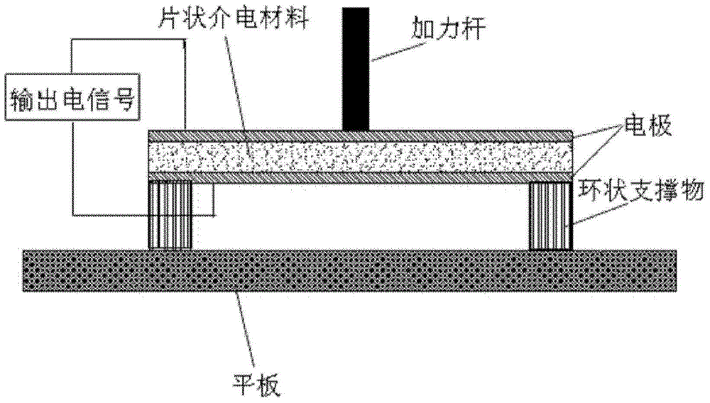
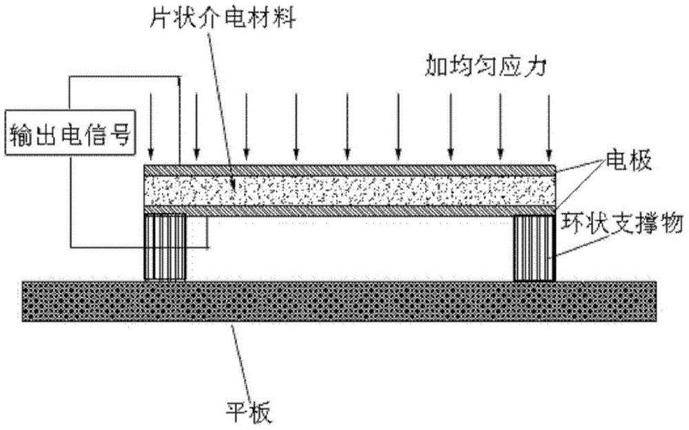
[0029] Embodiment 1: Utilize the purchased soft ferroelectric ceramic lead zirconate titanate (PZT-51) (Zibo Bailing Functional Ceramics Co., Ltd.), with a diameter of 25 millimeters and a thickness of 0.5 millimeters, to grind both sides of the ceramics flat, and use ions on both sides Gold electrodes are plated by sputtering, and then placed on a ring with a diameter of 20 mm and a flat plate with a side length of about 30 mm, and a little force is applied to the upper surface of the ceramic sheet, using ZJ-6A quasi-static d 33 The apparent piezoelectric performance of 38pC / N was obtained by instrument measurement.

Embodiment 2

[0030] Embodiment 2: utilize traditional solid-phase synthesis method to prepare 0.92Na 1 / 2 Bi 1 / 2 TiO 3 -0.08BaTiO 3 ceramics. A certain percentage of Bi 2 o 3 , Na 2 CO 3 , BaCO 3 ,TiO 2 (Analytical grade, Sinopharm Group) was added into alcohol ball mill for 6-8 hours, dried, and synthesized at 850°C for 2 hours. Then the synthesized powder is ball-milled, added with a suitable binder, pressed into a disc with a diameter of 25.4 mm, kept at 1180-1200° C. for 1 hour and sintered with a diameter of about 21 mm. Grind both sides of the ceramic sheet to a thickness of about 0.5 mm, plate gold electrodes on both surfaces by ion sputtering, and then place them on a ring with a diameter of 20 mm and a flat plate with a side length of about 30 mm , using the ZJ-6A quasi-static d 33 The apparent piezoelectric performance of 2-3pC / N was measured by the instrument.

Embodiment 3

[0031] Example 3: BaTiO prepared by traditional solid-phase synthesis 3 ceramics, a certain proportion of BaCO 3 ,TiO 2(Analytical grade, Sinopharm Group) was added into alcohol ball mill for 6-8 hours, dried, and synthesized at 1200°C for 2 hours. Then ball mill the synthesized powder, add appropriate binder, and press it into a disc with a diameter of 25.4 mm. After sintering at 1300°C for 2 hours, the diameter is about 21 mm, and the ceramic sheet is ground on both sides to a thickness of about 0.5 mm, gold electrodes are plated on both surfaces by ion sputtering, and then placed on a ring with a diameter of 20 mm and a flat plate with a side length of about 30 mm, using ZJ-6A quasi-static d 33 The apparent piezoelectric performance of 60-100C / N is obtained by instrument measurement.


PUM

PropertyMeasurementUnit
thicknessaaaaaaaaaa
heightaaaaaaaaaa
diameteraaaaaaaaaa

Abstract

The invention provides one kind of deflection voltage electric composite materials. The composite materials comprise sheet-shape dielectric materials, two electrodes, an annular supporter and a slab. The sheet-shape dielectric materials are clamped between the two electrodes to form sheet-shape dielectric materials provided with the electrodes. The annular supporter is positioned between the slab and the sheet-shape dielectric materials provided with the electrodes, and is in contact with the edges of the lab and the sheet-shape dielectric materials provided with the electrodes. According to the deflection voltage electric composite materials of the invention, by means of applying forces of one side of the sheet-shape dielectric materials, the sheet-shape dielectric materials can be bent or deformed in a bending-like mode. Strain gradient and deflection electric responses are generated on the thickness direction of the sheet-shape dielectric materials so as to generate piezoelectric effects.

Description

technical field [0001] The invention belongs to the field of functional materials, and mainly relates to the design of a piezoelectric composite material with a simple structure based on the flexoelectric effect. Background technique [0002] Piezoelectric effect, that is, a material responds with polarization when subjected to pressure (direct piezoelectric effect) or strain response under an electric field (inverse piezoelectric effect). The conversion between mechanical energy and electrical energy can be realized through the piezoelectric effect. At present, piezoelectric materials such as lead zirconate titanate ceramics (PZT) have been widely used to prepare devices such as sensors, drivers, transducers and energy recovery, and have very important applications in the fields of civil and national defense. In recent years, with the rapid development of science and technology, the service conditions of piezoelectric materials are also facing more and more challenges, suc...

Claims


Application Information

Patent Timeline
Patent Type & Authority Applications(China)
IPC IPC(8): H01L41/053H01L41/187H01L41/113C04B41/88C04B35/462C04B35/468
Inventor 初宝进周万丰潘祺章小同
Owner UNIV OF SCI & TECH OF CHINA
Why Eureka
Try Eureka