Dielectric-filled circular waveguide circularly polarized antenna

A technology of medium-filled waveguide and circularly polarized antenna, which is applied in the direction of antenna grounding switch structure connection, radiation element structure, etc., can solve the problem of few technical means for medium-filled waveguide antenna circular polarization, and achieve good consistency and reduce Small transition lengths, easy-to-achieve effects

Inactive Publication Date: 2015-11-04
10TH RES INST OF CETC
View PDF3 Cites 15 Cited by
  • Summary
  • Abstract
  • Description
  • Claims
  • Application Information

AI Technical Summary

Problems solved by technology

Dielectric-filled waveguide antenna is also a commonly used form of miniaturized antenna. Compared with microstrip antenna, it has the advantages of high efficiency, wide frequency ba

Method used


Image

  • Dielectric-filled circular waveguide circularly polarized antenna
  • Dielectric-filled circular waveguide circularly polarized antenna
  • Dielectric-filled circular waveguide circularly polarized antenna

Examples


Embodiment Construction

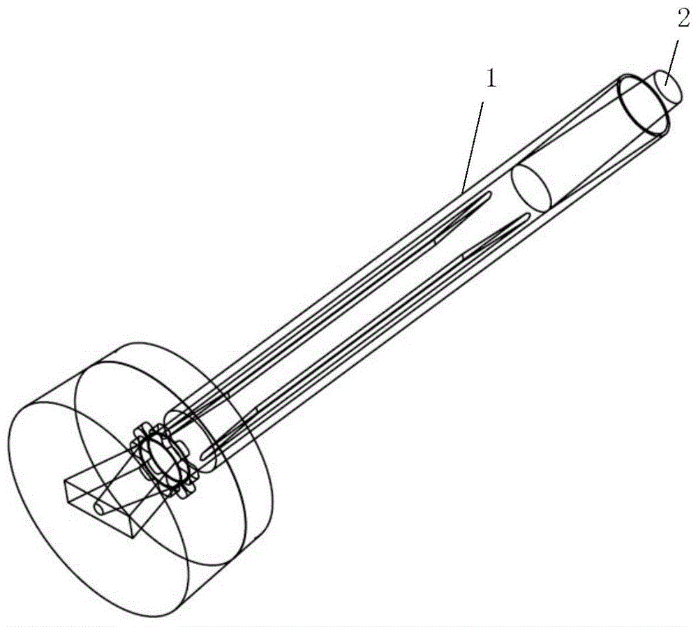
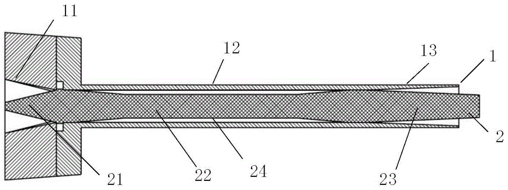
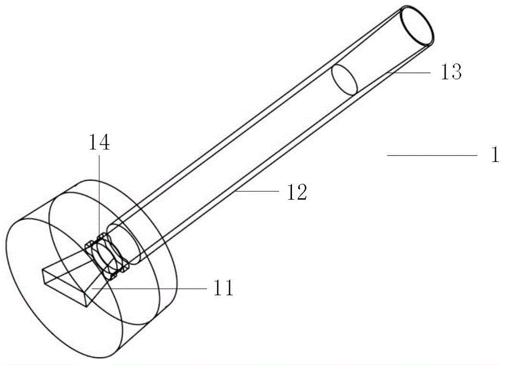
[0020] refer to Figure 1-Figure 3 . In an embodiment described below, a dielectric-filled waveguide circularly polarized antenna includes a hollow waveguide cavity 1 with a cylindrical platform, and a dielectric rod 2 with a mounting flange. Wherein, the feeding end and the radiating end of the dielectric rod (2) adopt a tapered tapered structure to realize matching. The waveguide cavity 1 is formed by connecting a dielectric circular waveguide and a conical horn. The rear end of the waveguide cavity 1 is formed with a circular frustum and a tapered tapered waveguide 11 at the center of the circular frustum. The tapered tapered waveguide with a rectangular end face transitions to a circular waveguide cavity 12. After the extension section, the conical horn 13 is connected to form the antenna feeding section. The feeding end of the rear section of the dielectric rod 2 filled in the waveguide cavity 1 is formed with a conical gradient feeding matching section 21, and the radia...


PUM


Abstract

The invention provides a dielectric-filled circular waveguide circularly polarized antenna, and includes a waveguide cavity (1) with a circular truncated cone and a dielectric rod (2) filled in the waveguide cavity. The waveguide cavity is formed by connecting a dielectric circular waveguide and a conical horn, a circular truncated cone and a rectangular end face tapered gradation waveguide (11) at the center of the circular truncated cone are manufactured on a rear end of the waveguide cavity, after transition to a circular waveguide (12) extending section, the rectangular end face taper gradation waveguide is connected with the conical horn (13) to form an antenna feed section which is filled in a feed end of a rear section of the tail of the dielectric rod in the waveguide cavity, a conical gradation feed matching section (21) and a front part front section radiation end are manufactured, a radiation matching section (23) formed by a circular truncated cone gradation transition section is manufactured, and a pair of radially symmetric air grooves (24) are manufactured on a cylinder of a circular polarizer (22) located in the middle of the dielectric rod (2), so as to realize a linear polarization-to-circular polarization function. The dielectric-filled circular waveguide circularly polarized antenna provided by the invention is particularly suitable for serving as an aperture-downsized circularly polarized waveguide antenna.

Description

technical field [0001] The invention relates to a medium-filled circular waveguide circularly polarized antenna, which is especially suitable for waveguide circularly polarized antennas with wide band and miniaturized aperture. Background technique [0002] When the polarization characteristics of the target are unknown, dual circularly polarized antennas are generally used for reception. However, the polarization isolation of dual circularly polarized antennas is often not ideal in a wide frequency band. Antenna Composition The simplest way to realize a circularly polarized antenna is to maintain a 90° phase difference in the feeding phase of two orthogonal dipole element pole antennas. Although this kind of antenna has a good axis ratio of circular polarization in the axial direction, it has a poor ratio of circular polarization axes at a large angle away from the axial direction. As we all know, the plane and plane pattern of the corrugated horn are well equalized, and ...

Claims


Application Information

Patent Timeline
IPC IPC(8): H01Q1/36H01Q1/50
Inventor 刘熠志刘波陈福林
Owner 10TH RES INST OF CETC
Why Eureka
Try Eureka