Brake actuation unit

A braking operation unit, electric operation technology, applied in the direction of brakes, braking action starting devices, braking transmission devices, etc., can solve problems such as inapplicability, and achieve the effect of improving availability

Active Publication Date: 2015-11-04
CONTINENTAL AUTOMOTIVE TECH GMBH
View PDF10 Cites 21 Cited by
  • Summary
  • Abstract
  • Description
  • Claims
  • Application Information

AI Technical Summary

Problems solved by technology

Due to this limited availability of the brake actuating unit, the brake actua

Method used


Image

  • Brake actuation unit
  • Brake actuation unit
  • Brake actuation unit

Examples


Embodiment Construction

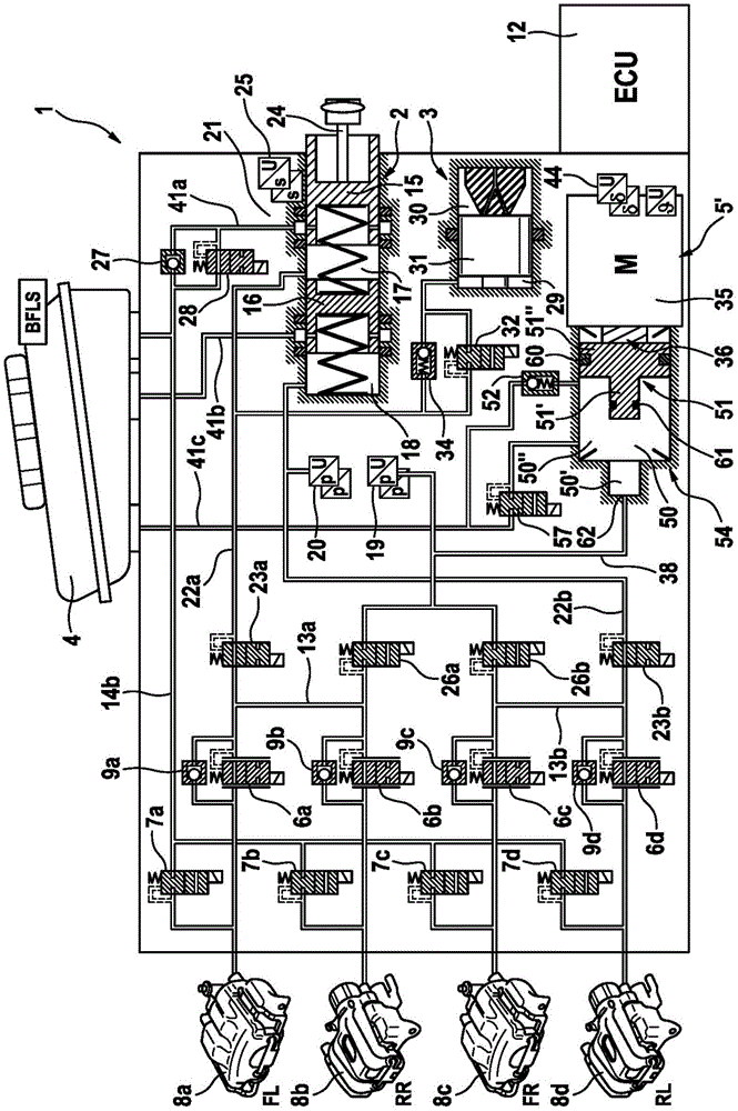
[0040] figure 1 shows very schematically a brake system for a motor vehicle with a first embodiment of the brake actuating unit according to the invention. The brake system shown comprises an exemplary brake actuating unit 1 and hydraulically actuated wheel brakes 8 a - 8 d connected to the brake actuating unit.

[0041] The brake actuating unit 1 basically comprises a brake master cylinder 2 , which can be actuated by means of an actuating pedal or brake pedal not shown, a pedal travel simulator (simulator device) 3 cooperating with the brake master cylinder 2 , A pressure medium reservoir 4 at atmospheric pressure assigned to the brake master cylinder 2, an electrically controllable pressure supply device 5, a first set of electrically operable valves 6a to 6a for adjusting the wheel-specific brake pressure 6d, 7a-7d, a second set of electrically operable valves 23a, 23b, 26a, 26b for disconnecting or connecting the wheel brakes 8a-8d to the master cylinder 2 or to the pres...


PUM


Abstract

The invention relates to a brake actuation unit (1) for a "brake-by-wire" motor vehicle brake system, comprising: a brake pedal-actuatable master brake cylinder (2) and an associated pressure-medium reservoir (4); an electrically controllable pressure provision device (5), which is formed by a hydraulic cylinder/piston assembly, the piston (51) of which can be actuated by an electric motor (35), wherein the piston delimits a pressure chamber (50), which is sealed off from the atmosphere by a main sealing element (60); a first group of electrically actuatable valves (6a-6d, 7a-7d) for adjusting respective braking pressures for each wheel; a second group of electrically actuatable valves (23a, 23b, 26a, 26b) for disconnecting the wheel brakes from or connecting the wheel brakes to the master brake cylinder or the pressure provision device; and an electronic open-loop and closed-loop control unit (12, 12'). The pressure chamber (50) is sealed by an additional sealing element (61) after a specified actuation of the piston (51). The electric motor has at least two drive units operable independently of one another, each having at least one winding, for driving the rotor of the electric motor. The electronic open-loop and closed-loop control unit comprises a first microcontroller (201) and a second microcontroller (301). The first microcontroller is designed to control (205) one of the drive units of the electric motor and the second microcontroller is designed to control (305) the other of drive units of the electric motor, and the first and second microcontrollers are designed to control (207, 307) the second group of valves.

Description

technical field [0001] The invention relates to a brake actuating unit according to the preamble of claim 1 . Background technique [0002] Braking systems of the "brake-by-wire" type are becoming more and more popular in motor vehicle technology. Such braking systems generally include not only a brake master cylinder that can be actuated by the vehicle driver, but also an electrically controllable pressure supply device, by means of which the wheel brakes are actuated in the "brake-by-wire" operating mode. operate. [0003] A brake actuating unit for a "brake-by-wire" motor vehicle brake system is known from the international patent application WO 2013 / 023953 A1. In this case, a brake master cylinder, actuatable by a brake pedal, to which the wheel brakes of the motor vehicle can be connected, is provided in one unit; an electrically controllable pressure supply device, which is configured as A hydraulic cylinder-piston arrangement, the piston of which can be moved by me...

Claims


Application Information

Patent Timeline
IPC IPC(8): B60T13/68B60T13/74B60T13/66
CPCB60T8/321B60T8/4081B60T2270/82B60T7/042B60T7/12B60T8/171B60T11/103B60T11/224
Inventor J·库尔巴萨H-J·法伊格尔
Owner CONTINENTAL AUTOMOTIVE TECH GMBH
Why Eureka
Try Eureka