
Cooling mechanism for data center

A technology for cooling mechanisms and data centers, applied in refrigerators, irreversible cycle compressors, cooling/ventilation/heating renovation, etc. cost, effect of preventing temperature rise, and reducing operating cost

Inactive Publication Date: 2015-11-04
金尾 英敏
View PDF7 Cites 3 Cited by
  • Summary
  • Abstract
  • Description
  • Claims
  • Application Information

AI Technical Summary

Problems solved by technology

[0005] However, the cooling mechanism of such a mode has the following problems: the blowing volume is huge and the blowing distance is long, so the power consumption of the blower is very large; a large space is required for the blowing; The space is all cooled, so there will be temperature inhomogeneities, etc.
[0006] In addition, in addition to the above-mentioned methods, there are actually water-cooled cooling mechanisms that form a circulation path around the heat sink and circulate the cooling medium in the circulation path, but such water-cooled cooling mechanisms cannot be completely ruled out. There is a risk of damage to IT equipment in the event of liquid leakage, so it is not necessarily suitable for data centers that require stability and reliability
[0007] As mentioned above, in the current situation, in order to operate the data center stably, no cooling mechanism has been found that sufficiently satisfies the following two conditions: preventing the entry of dust, generation of water droplets, and leakage of water; and reducing the operation of power, etc. cost
[0008] In addition, when a fire breaks out in the data center due to electric leakage, etc., sprinkler equipment is used to release water, so there is also a problem that not only the equipment near the fire cannot be used, but also other equipment cannot be used, resulting in a huge data disappear

Method used


Image

  • Cooling mechanism for data center
  • Cooling mechanism for data center
  • Cooling mechanism for data center

Examples


Embodiment

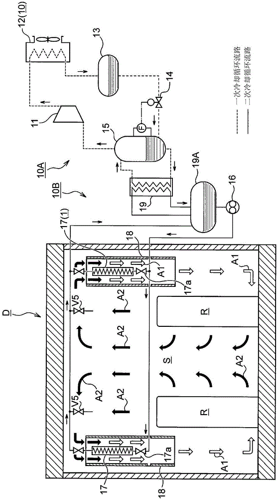
[0048] First, the data center D to which the present invention is applied is a facility in which many IT devices such as servers and network devices are housed in appropriate racks. Herein, regarding the above-mentioned IT equipment, it is referred to as heat dissipation equipment R hereinafter in view of its heat dissipation characteristics.

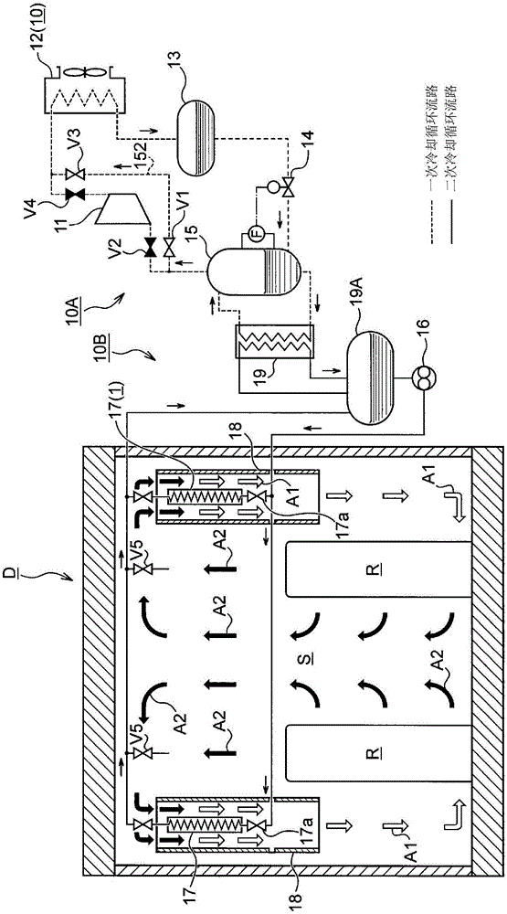
[0049] The cooling mechanism 1 of the data center D of the present invention (hereinafter referred to simply as the cooling mechanism 1) is constituted as follows: an evaporative condenser 12 and a liquid receiver are arranged outside the data center D; S is equipped with an evaporator 17, and the indoor space S (radiation device R) is cooled by cold air A1 generated by the evaporation of the refrigerant in the evaporator 17, and the evaporative condenser 12 is used for cooling. agent condensation.

[0050] In addition, in the following as a basic embodiment ( figure 1 , figure 2 ) The cooling mechanism 1 to be described in ) is co...


PUM


Abstract

[Problem] To develop a novel data center cooling mechanism which can be operated at a low running cost, and with which the infiltration of dirt and dust, the generation of water droplets, and water leakage can be eliminated, and temperature variations in the spaces in a room can be reduced, and with which a fire can be extinguished quickly and with little damage when a fire occurs. [Solution] A data center cooling mechanism characterized in that an evaporative condenser and a liquid receiver are arranged outside of a data center room, an evaporator is arranged in a space inside the data center room, and the space inside the room is cooled by evaporation of a refrigerant in the evaporator, with the refrigerant being condensed by the evaporative condenser.

Description

technical field [0001] The invention relates to a cooling mechanism of a data center, in particular to a cooling mechanism of a data center capable of significantly reducing power consumption. Background technique [0002] In a data center where many IT devices (cooling devices) such as servers and network devices are installed, in order to operate the IT devices stably, it is necessary to use a cooling mechanism for cooling so that the temperature of the data center does not become the specified temperature ( 27 ℃ ~ 30 ℃ or so) above. [0003] In the indoor space of such a data center, except for maintenance, there is very short time for people, and the amount of air exchange is also small, so the latent heat load is low. On the other hand, the heat dissipation from the cooling equipment is large, so the sensible heat The load is high, and there is a load in the entire indoor range. [0004] Therefore, currently, as the cooling mechanism, a structure in which cool air gen...

Claims


Application Information

Patent Timeline
Patent Type & Authority Applications(China)
IPC IPC(8): F24F7/06F25B1/00F25B1/053F25B39/02
CPCH05K7/20827F25B25/005H05K7/20309H05K7/20318
Inventor 白岩宽之金尾英敏
Owner 金尾 英敏
Learn More