An automatic cleaning device for photovoltaic modules

A photovoltaic module and automatic cleaning technology, applied in the fields of photovoltaic modules, photovoltaic power generation, and cleaning methods using tools, etc., can solve the problems of reducing the power generation of components, the cleaning effect is general, and the loss of power generation, so as to simplify the structural components of the device and ensure the The effect of running stability and improving power generation efficiency

Active Publication Date: 2017-07-25
江苏长江环境科技工程有限公司
View PDF1 Cites 1 Cited by
  • Summary
  • Abstract
  • Description
  • Claims
  • Application Information

AI Technical Summary

Problems solved by technology

At present, due to air smog, dust and other reasons, there will be dust or stains on the built-up photovoltaic panels, which will reduce the intensity of light irradiation and reduce the power generation of modules. while creating a safety hazard
This will inevitably involve the cleaning of components. Due to the difficulty of manned operation on the top surface and other harsh natural environments such as unsafe human operation environment, severe water shortage, and excessive workload, how to regularly clean the photovoltaic panels of photovoltaic power plants, so that Operators of photovoltaic power plants are quite a headache
Currently commonly used component cleaning methods are: 1. Natural flushing with rainwater, low cost, completely dependent on natural climate, cleaning is not clean; 2. Manual cleaning, the most common, good cleaning effect, high labor cost, difficult to organize, not suitable for roof component cleaning ;3. High-pressure water gun cleaning, which is costly and clean but easy to damage components; 4. Spray system cleaning, the cleaning effect is average, and requires initial cost investment; 5. Professional cleaning vehicles, good cleaning effect and high cost, are only suitable for Ground Power Station for Traffic Conditions

Method used


Image

  • An automatic cleaning device for photovoltaic modules
  • An automatic cleaning device for photovoltaic modules
  • An automatic cleaning device for photovoltaic modules

Examples


Embodiment Construction

[0029] The present invention will be further described below in conjunction with accompanying drawing.

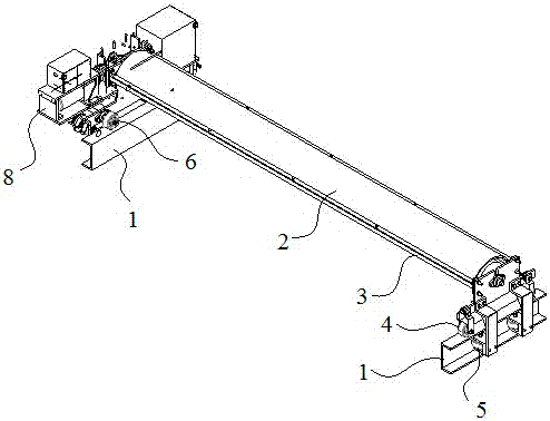
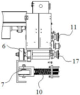
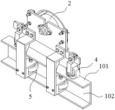
[0030] Such as figure 1 , figure 2 , image 3 , Figure 4 and Figure 5 As shown, the automatic cleaning device for photovoltaic modules of the present invention mainly includes a track, a cleaning structure, a driving and walking structure, and the like. The track includes two tracks 1, which are symmetrically arranged on both sides of the photovoltaic module. The track 1 includes at least a running plane 101 on the top and a balance groove 102 on the side. A typical track 1 structure can use I-shaped steel . The cleaning structure includes a cleaning shaft 2 and a cleaning brush 3 arranged on the cleaning shaft 2. The cleaning shaft 2 is set between two rails 1 and is located above the photovoltaic module. The cleaning brush is driven by rotation to clean the surface of the photovoltaic module.

[0031] The driving walking structure includes traveling wheels, balan...


PUM


Abstract

The invention discloses an automatic cleaning device of a photovoltaic module. The automatic cleaning device comprises rails, a cleaning shaft, a cleaning brush, walking wheels, balance wheels and a motor, wherein two rails are provided, and are symmetrically arranged at the two sides of the photovoltaic module in parallel; the walking wheels and the balance wheels are respectively arranged at the two sides of the cleaning shaft, and are both arranged on the rails; the walking wheels at one side are driven by the motor; the motor drives the cleaning shaft to rotate while driving the walking wheels to walk through a multifunctional shaft; and the cleaning brush is arranged on the cleaning shaft. The automatic cleaning device is simple in structure; the multifunctional shaft is adopted to synchronously drive the cleaning shaft and the walking wheels, so that structural parts of the device are effectively simplified, and a synchronization function is realized; the multifunctional shaft has a self-locking function to effectively stop the slip of the cleaning device caused by inclined installation of the photovoltaic module; and adjusting springs are arranged on the balance wheels for effectively balancing torsional cutting force generated by desynchrony of active walking and passive walking of the balance wheels, so that the walking stability of the device is guaranteed, and the service life of the product is prolonged.

Description

technical field [0001] The invention relates to the technical field of supporting photovoltaic solar power generation equipment, in particular to an automatic cleaning device for photovoltaic modules. Background technique [0002] At present, the construction of photovoltaic power plants has entered the distributed era, and the policy encourages everyone to use idle roofs, agricultural greenhouses and other buildings or top resources of appendages to build distributed photovoltaic power plants. At present, due to air smog, dust and other reasons, there will be dust or stains on the built-up photovoltaic panels, which will reduce the intensity of light irradiation and reduce the power generation of modules. At the same time, it will cause safety hazards. This will inevitably involve the cleaning of components. Due to the difficulty of manned operation on the top surface and other harsh natural environments such as unsafe human operation environment, severe water shortage, an...

Claims


Application Information

Patent Timeline
Patent Type & Authority Patents(China)
IPC IPC(8): B08B1/04B08B11/04H02S40/10
CPCB08B1/002B08B1/04B08B11/04H02S40/00Y02E10/50
Inventor 施爱萍谢振国杜邱资卞慧昀张梦锦张慧
Owner 江苏长江环境科技工程有限公司
Why Eureka
Try Eureka