Cloth and yarn cutting-off machine with dust removal function

A cutting machine and fabric technology, which is applied in the field of fabric and yarn fiber processing and dust removal, can solve the problems of harm, pollute the environment, human body, and no dust removal by the rag machine, and achieve the effect of simple and practical structure.

Active Publication Date: 2015-11-11
绵阳光益生物科技有限公司
View PDF7 Cites 2 Cited by
  • Summary
  • Abstract
  • Description
  • Claims
  • Application Information

AI Technical Summary

Problems solved by technology

[0003] Existing fabric and yarn cutting machines such as figure 1 As shown, a large amount of dust will be produced in the production process, which will not only pollute the environment but also cause great harm to the human body, and easily cause fires
However, the existing rag machine does not have the function of dust removal, which causes serious harm to this problem.

Method used


Image

  • Cloth and yarn cutting-off machine with dust removal function
  • Cloth and yarn cutting-off machine with dust removal function
  • Cloth and yarn cutting-off machine with dust removal function

Examples


Embodiment 1

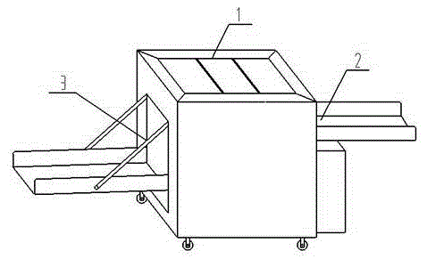
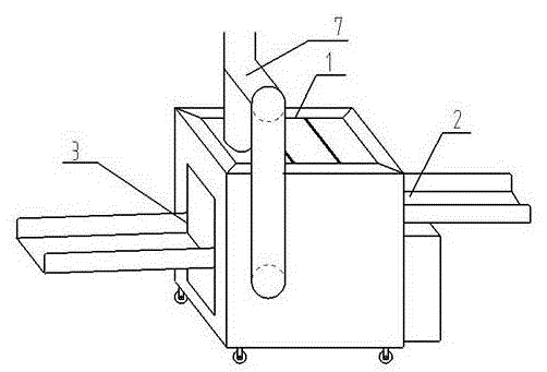
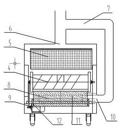
[0021] Such as Figure 2-4 A cloth and yarn cutting machine with dust removal function shown includes a cutting machine casing 1, a feeding port 2, a discharging port 3 and a rotary hob 4, and the feeding port 2 is arranged at the front end of the cutting machine casing 1. The discharge port 3 is arranged on the rear end of the cutting machine casing 1, the rotary hob 4 is arranged in the cutting casing 1, and a dust filter plate 5 is arranged in the cutting machine casing 1 above the rotary hob 4, and a dust filter plate 5 is arranged on the top of the dust filter plate 5 The top dust discharge port 6 is arranged on the cutting machine box body 1, and the top dust discharge port 6 is connected with a dust discharge pipe 7; the cloth and yarn enter the cutting machine box body 1 through the feed port 2, and are continuously cut by the rotating hob 4 Next, the cloth and yarn will be cut or crushed into small pieces. At the same time, the dust generated during the crushing proce...

Embodiment 2

[0023] Such as Figure 2-5 A cloth and yarn cutting machine with dust removal function is shown, on the basis of Embodiment 1, in order to more effectively discharge the dust in the cut cloth and yarn under the rotary hob 4, the bottom of the rotary hob 4 A drum-type dust cage 8 is provided in the cutting machine box 1, and the drum-type dust cage 8 is placed on two rotating shafts 12 to roll, and the drum-type dust cage 8 is supported by the two rotating shafts 12, and the two rotating shafts 12 are in the motor 9 is driven to rotate, and the rotation of the two rotating shafts 12 drives the drum-type dust cage 8 to rotate. The drum-type dust cage 8 is provided with a dust-absorbing inner tank 11, and the dust-absorbing inner tank 11 is connected with the dust-absorbing pipeline 7 is connected and fixed, and the drum-type dust cage 8 is driven by two rotating shafts 12 to rotate continuously. The dust-absorbing liner 11 in the drum-type dust cage 8 remains fixed. The side du...

Embodiment 3

[0026] Such as Figure 2-4 A cloth and yarn cutting machine with dust removal function shown, on the basis of Embodiment 1, the side dust discharge port 10 is connected with a dust discharge pipe 7, and the dust discharge pipe 7 and the top dust discharge port 6 pass through The three-way pipe connection is convenient for dust discharge, and the structure is practical and simple. The top dust discharge port 6 and the side dust discharge port 10 are used to discharge through a main pipe.


PUM

PropertyMeasurementUnit
diameteraaaaaaaaaa
diameteraaaaaaaaaa

Abstract

The invention discloses a cloth and yarn cutting-off machine with a dust removal function. The cloth and yarn cutting-off machine comprises a cutting-off machine box, a feeding port, a discharging port and a rotating hob. The feeding port is formed in the front end of the cutting-off machine box. The discharging port is formed in the rear end of the cutting-off machine box. The rotating hob is arranged in the cutting-off machine box. A dust filtering plate is arranged on the portion, above the rotating hob, in the cutting-off machine box. A top dust discharge port is formed in the portion, above the dust filtering plate, of the cutting-off machine box and connected with a dust discharge pipeline. The situation that when the cloth and yarn cutting-off machine works, dust flies everywhere and has a serious impact on human bodies and environment is improved, after the technical scheme is adopted, the dust removal rate can be 90% or over 90%, and the structure is simple and practical.

Description

technical field [0001] The invention relates to the field of dust removal for cloth and yarn fiber processing, in particular to a cloth and yarn cutting machine with dust removal function. Background technique [0002] Due to the continuous development and progress of science and technology and human material civilization, various new production materials are constantly emerging, and with the production of new materials, a large number of waste products or products that need to be reprocessed will be produced. It is an inevitable demand for regeneration and recycling, because the environmental protection effect and benefit effect produced by the processing object are obvious. Just talking about soft fiber products and textile materials, the rag machine can be said to play a huge role that cannot be ignored. Because the fiber And the fiber structure of textiles and leather products is criss-crossed, the structure is tight, the tensile strength is very high, and the special so...

Claims


Application Information

Patent Timeline
Patent Type & Authority Applications(China)
IPC IPC(8): D06H7/00B01D50/00
Inventor 郑吕军
Owner 绵阳光益生物科技有限公司
Why Eureka
Try Eureka