Overlapped floor

A technology of laminated floors and slabs, applied in floors, building components, buildings, etc., can solve the problems of increasing the weight of laminated slabs, application impact, and limited bearing capacity of prefabricated floors, so as to reduce self-weight, reduce consumption, and improve thermal insulation effect of ability

Active Publication Date: 2015-11-11
HUNAN DONGFANGHONG CONSTR GRP
View PDF10 Cites 15 Cited by
  • Summary
  • Abstract
  • Description
  • Claims
  • Application Information

AI Technical Summary

Problems solved by technology

However, in the currently commonly used assembled monolithic reinforced concrete laminated floors, the bearing capacity of the prefabricated floor is limited. When the span exceeds 3m, it is necessary to add support or thicken the floor. At the same time, the connecting nodes between the plate and the surrounding beams (or walls) The shearing is mainly borne by the post-casting layer of the laminated slab, which also makes the thickness of the post-casting laminated layer increase with the increase of the slab span, which will inevitably increase the self-weight of the laminated slab, so that in the long-span floor Apps in are affected

Method used


Image

  • Overlapped floor
  • Overlapped floor
  • Overlapped floor

Examples


Embodiment 1

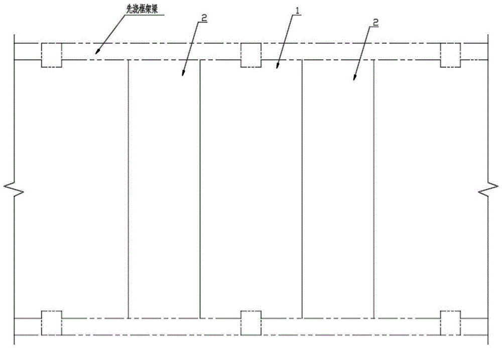
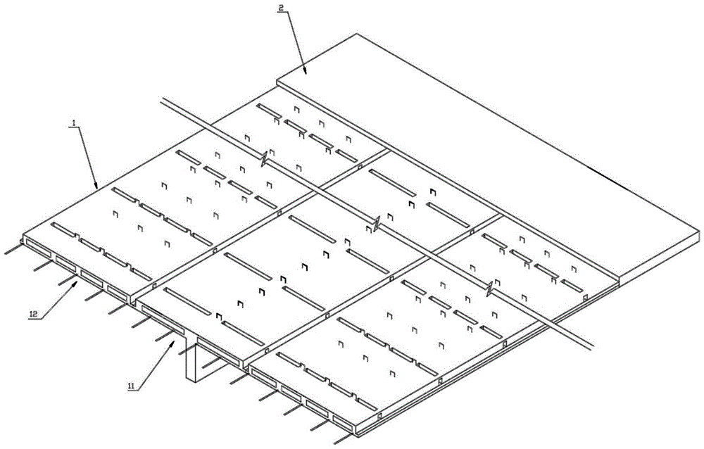
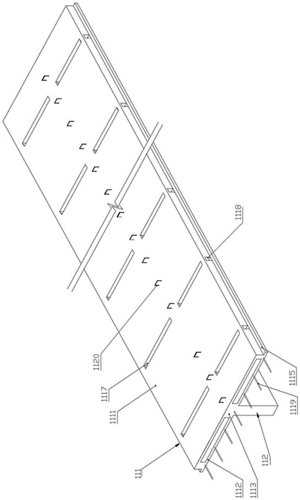
[0023] Embodiment one, such as Figure 2-4 As shown, this preferred embodiment discloses a laminated floor slab I, which includes a prefabricated layer I1 and a post-cast laminated layer I2 above it. The prefabricated layer I1 includes a T-beam slab I11 and a flat plate I12 equal in length to it. The flat plate I12 is arranged On both sides of T beam plate I11. The T beam plate I11 is a T-shaped integral prefabricated part of the horizontal roof I111 and the vertical beams 112 arranged below it along its length direction. The horizontal roof I111 is a frame structure surrounded by the upper panel I1111, the lower panel I1112 and the intersecting longitudinal ribs I1113 and transverse ribs I1114 between them, and the two sides of the lower panel I1112 have flanges along the length direction 1115, the longitudinal rib belt I1113 and the transverse rib belt I1114 are respectively arranged between the upper panel 1111 and the lower panel I1112 along the length direction and the w...

Embodiment 2

[0029] Embodiment two, such as Figure 5 As shown, this preferred embodiment discloses a laminated floor slab II, which differs from the first embodiment in that: in the horizontal roof of the T-beam slab II 101 and the flat plate II 102, the two sides in the width direction and the adjacent longitudinal ribs II 1011 The distance between them is smaller than the distance between two adjacent longitudinal ribbed strips II1011, and the other independent cavities except the independent cavities on both sides in the width direction are filled with corresponding filling blocks 1116; between two adjacent transverse ribbed strips II1012 In the area of ​​each longitudinal rib belt, there is a vertical rib groove 1014 opening upward, and the longitudinal rib belt II 1011 is provided with a longitudinal rib beam reserved hole II 1013 running through it in the longitudinal direction. Other structures and usages of this embodiment are the same as those in Embodiment 1.

Embodiment 3

[0030] Embodiment three, such as Figure 6 As shown, this preferred embodiment discloses a laminated floor slab III, which includes a prefabricated layer IIIA and a post-cast laminated layer IIIB above it. The prefabricated layer IIIA includes a T-beam slab IIIIA1 and a flat plate IIIA2 with the same length as the flat plate IIIA2. On both sides of T beam plate IIIA1.

[0031] The T beam plate IIIA1 is a T-shaped integral prefabricated part of the horizontal roof IIIA11 and the vertical beam IIIA12 arranged below it along its length direction.

[0032] The flat plate ⅢA2 includes the bottom panel ⅢA21 and the filling block ⅢA22. In order to ensure the effect of thermal insulation, the filling block ⅢA22 is made of light thermal insulation material; A transverse rib band IIIA23 is formed between two adjacent columns, and a longitudinal rib band IIIA24 is formed between two adjacent columns. There is a certain distance between the outer ends of the outermost two columns of the ...


PUM


Abstract

The invention discloses an overlapped floor which comprises a plurality of prefabricated reinforced concrete panels and T beam plates. At least one panel is spliced between every two adjacent T beam plates, and the prefabricated reinforced concrete panels and the T beam plates form the integral overlapped floor through post-poured reinforced concrete overlapped layers. According to the overlapped floor, due to the prestress technology and a bidirectional dense rib sandwiching structure form, the use amount of concrete is reduced, dead load is reduced, cost is reduced, and the rigidity and the bearing force of the overlapped floor are improved. Longitudinal rib belts and transverse rib belts are poured through lightweight aggregate structure heat insulation concrete so that the thermal bridge influences on the longitudinal rib belts and the transverse rib belts can be reduced, and meanwhile light filling blocks are matched for improving the heat insulation capability of the overlapped floor. When the overlapped floor is used, the T beam plates and the panels are arranged on a pre-pouring frame beam, and then the integral overlapped floor is formed after post-pouring of the reinforced concrete overlapped layers. The dead load is not increased, the bearing force is ensured, the shearing resisting capability of connecting points is ensured, and meanwhile heat preservation and heat insulation can be achieved; under the premise that the integrity and safety of the overlapped floor are ensured, the construction cost is reduced, and construction is simplified.

Description

technical field [0001] The invention relates to a floor slab, in particular to a laminated floor slab. Background technique [0002] As building energy-saving standards increase from 50% energy saving to 65% energy saving, the heat transfer coefficient K of the individual floor slabs in the envelope structure is also included in mandatory terms. Therefore, the energy-saving design and construction of individual floor slabs is imperative. At the same time, with the promulgation and implementation of the industry standard "Technical Regulations for Prefabricated Concrete Structures" JGJ1-2014 of the Ministry of Housing and Urban-Rural Development, the industrialization of buildings will develop rapidly. The advantages of both the integral type and the prefabricated assembly type not only save templates, reduce engineering costs, but also ensure the integrity and earthquake resistance of the floor, and are increasingly used in modern civil engineering. However, in the currentl...

Claims


Application Information

Patent Timeline
Patent Type & Authority Applications(China)
IPC IPC(8): E04B5/19
Inventor 龚友平龚有才龚文彦郑智洪欧长红伍丹
Owner HUNAN DONGFANGHONG CONSTR GRP
Why Eureka
Try Eureka