

Damping balance valve
A balancing valve and damping technology, applied in the field of damping balancing valve, can solve the problems of insufficient hydraulic walking system, unsatisfactory controllability, large hydraulic impact force, etc., and achieve the effect of improving the smoothness of action, simple structure and eliminating pressure vibration.
- Summary
- Abstract
- Description
- Claims
- Application Information
AI Technical Summary
Problems solved by technology
Method used
Image

Examples
Embodiment Construction
[0015] Embodiments of the present invention will be described in further detail below in conjunction with the accompanying drawings.
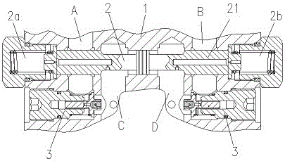
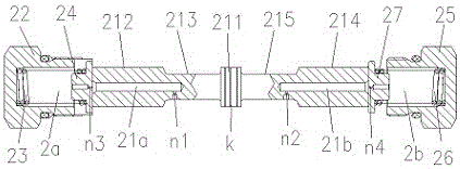
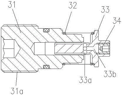
[0016] Figure 1 to Figure 3 It is a structural schematic diagram of the present invention.
[0017] The reference signs are: A track, B track, C track, D track, the first radial damping hole n1, the second radial damping hole n2, the first axial damping hole n3, the second axial damping hole n4 , valve body 1, balance spool group 2, left balance valve cavity 2a, right balance valve cavity 2b, balance spool 21, left axial pilot oil passage 21a, right axial pilot oil passage 21b, central annular platform 211, storage Oil lubrication groove k, left sealing shaft section 212, left groove section 213, right sealing shaft section 214, right groove section 215, left spring seat 22, left spring 23, left valve seat 24, right spring seat 25, right spring 26. Right valve seat 27, one-way throttle valve with detachable damping 3, one-way throttle valve ...
PUM
 Abstract
Description
Claims
Application Information