Machine vision-guided laser gear chamfering contour measurement apparatus and measurement method thereof

A technology of contour measurement and machine vision, applied in the direction of measuring devices, instruments, optical devices, etc., can solve the problems of the stability of measurement values ​​and the impact of measurement accuracy, and achieve low manufacturing costs, avoid system errors, and improve measurement accuracy. Effect

Inactive Publication Date: 2015-11-11
TIANJIN UNIV OF SCI & TECH +1
View PDF5 Cites 31 Cited by
  • Summary
  • Abstract
  • Description
  • Claims
  • Application Information

AI Technical Summary

Problems solved by technology

The patent number is: 2011102364117, and the name is: Gear Chamfering Laser Measuring Instrument The technical solution disclosed in the patent can measure multiple sections of a tooth, but the corresponding mandrel must be selected according to the diameter of the inner hole of the gear, and rely on the turntable and positioning Only the fixture can realize the positioning of the gear; after the measurement of multiple sections of a tooth is completed, the fixture needs to be adjusted according to the odd or even number of gear teeth, so that the measured tooth can be positioned under the measurement sensor, and then multiple sections of the next tooth can be carried out During the measurement of the chamfer profile, in the process of workpiece reloading, human factors will affect the measurement accuracy, and at the same time, the stability of the measured value will also be affected during the repeated measurement process

Method used


Image

  • Machine vision-guided laser gear chamfering contour measurement apparatus and measurement method thereof
  • Machine vision-guided laser gear chamfering contour measurement apparatus and measurement method thereof
  • Machine vision-guided laser gear chamfering contour measurement apparatus and measurement method thereof

Examples


Embodiment Construction

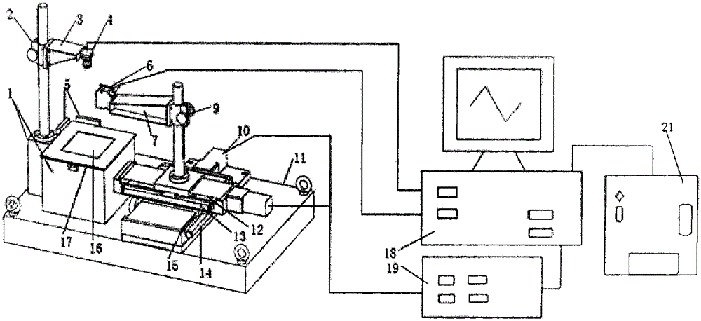
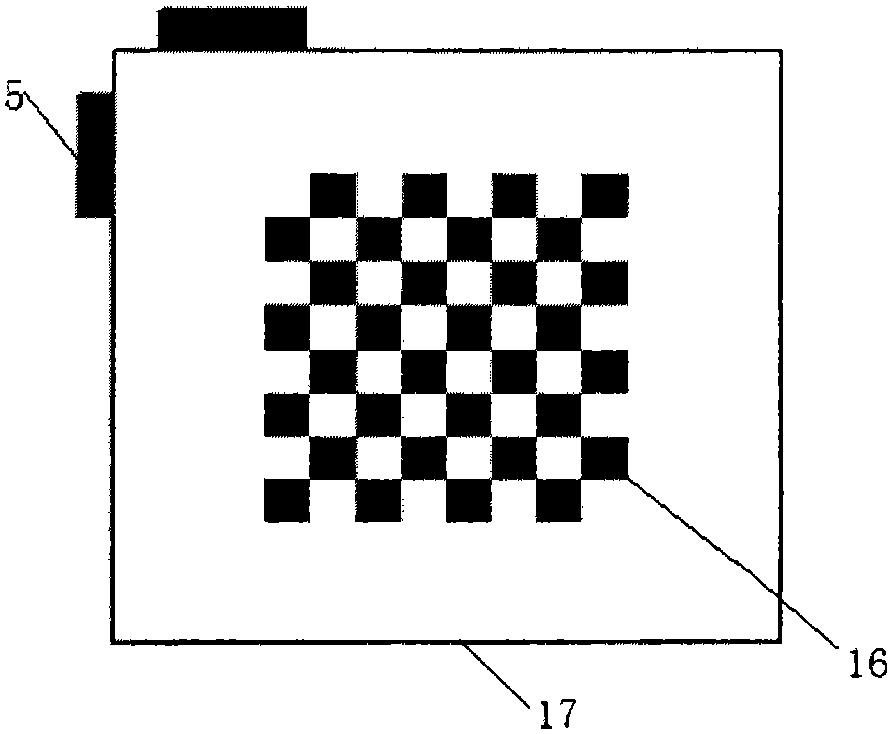
[0050] The invention provides a laser gear chamfer profile measuring instrument based on machine vision and its measurement method. An industrial camera is used to obtain the image of the gear under the backlight, and the position of the gear center is calculated by a calibration algorithm, and measured according to the gear chamfer According to the requirements, the X-Y platform drives the laser displacement sensor to measure the path, and finally carries the laser sensor along the measurement path to complete the contour numerical measurement in the Z direction, and the data is uploaded to the computer, showing the surface contour shape and related parameters of the gear chamfer.

[0051] The main parameters related to the surface profile of the measurable gear chamfer include: the angle of the forming section and its symmetry, the distance from the intersection line of the forming section to the specified surface, the radius of curvature of the arc chamfer, etc.; it has machi...


PUM


Abstract

The present invention provides a machine vision-guided laser gear chamfering contour measurement apparatus, which comprises a machine vision calibration device, a measurement workbench, a gear chamfering contour measurement device and a data acquiring and processing device. The machine vision calibration device comprises a light source module. The light source module is arranged on the measurement workbench. A Z-axis adjustment mechanism is arranged at one side of the measurement workbench. One end of the Z-axis adjustment mechanism is provided with an industrial camera. The industrial camera is connected with the data acquiring and processing device through a USB data line interface. The gear chamfering contour measurement device comprises an X-Y movement platform at one side of the measurement workbench. The Z-axis measurement workbench arranged on the X-Y movement platform is connected with the X-Y movement platform. The Z-axis measurement workbench is provided with a laser displacement sensor. The laser displacement sensor is connected with the data acquiring and processing device through a data line. The apparatus enables the non-contact type measurement, and is accurate in measurement result and low in manufacturing cost.

Description

technical field [0001] The invention belongs to the technical field of gear chamfering profile measurement, in particular to a laser gear chamfering profile measuring instrument based on machine vision guidance. Background technique [0002] Chamfered gears are one of the essential core components in gearboxes such as automobiles and construction machinery. They are components that realize shift guidance and motion transmission, and can reduce impact and vibration. At present, the shapes of chamfers mainly include: plane sharp corners, arc surface chamfers, pointed arch rounded corners and asymmetric chamfers, etc. Automobile gearboxes need to switch gears to achieve speed change according to different working conditions. Each switch is a process of disengagement and re-engagement of paired gears. When gears without chamfering are switched, impacts and collisions between paired gears are prone to occur. And re-engagement is difficult. The machining accuracy of the chamfer ...

Claims


Application Information

Patent Timeline
Patent Type & Authority Applications(China)
IPC IPC(8): G01B11/24
Inventor 许增朴霍津海王永强周聪玲于德敏杨书业
Owner TIANJIN UNIV OF SCI & TECH
Why Eureka
Try Eureka