A high-speed train car body stress test device and its working method

A technology of stress testing and high-speed trains, applied in the direction of measuring devices, measurement of the change force of optical properties of materials when they are stressed, instruments, etc., can solve the problems of maintenance personnel, evaluation of difficult welding joints, wiring confusion, etc. Achieve the effects of avoiding poor anti-electromagnetic interference ability, improving wiring difficulty, and convenient data processing

Active Publication Date: 2017-10-20
CHINA RAILWAYS CORPORATION
View PDF20 Cites 0 Cited by
  • Summary
  • Abstract
  • Description
  • Claims
  • Application Information

AI Technical Summary

Problems solved by technology

[0013] (1) Due to the large number of hangers in the equipment compartment under the vehicle, the monitoring system requires a large number of strain sensors to form a complex network system. Therefore, the monitoring network on a vehicle may have nearly a hundred sensors, which inevitably requires a There is a large space for wiring installation, which will make the already narrow equipment compartment more crowded, and the wiring will be chaotic, which will seriously affect the normal work of the maintenance personnel in the equipment compartment under the vehicle
[0014] (2) More importantly, due to the existence of high-intensity electromagnetic fields during the operation of high-speed trains and the interference of electromagnetic signals in the surrounding environment, the signal errors obtained by traditional electrical measurement tests are very large
However, the IIW standard only stipulates some overlapping forms of welded joints, it is difficult to evaluate the numerous complex welded joints of high-speed trains, and there is no effective solution for other unspecified weld forms

Method used


Image

  • A high-speed train car body stress test device and its working method
  • A high-speed train car body stress test device and its working method

Examples


Embodiment Construction

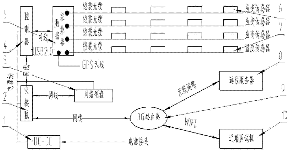
[0042] The present invention will be further described below in conjunction with the accompanying drawings. Such as Figure 1-2 As shown, a high-speed train body stress test device includes a strain sensor 6, a temperature sensor 7, a controller 4, a data collector 5, a switch 2, a network hard disk 3, a remote server 8, a near-end debugging machine 10, and a 3G router 9 and the power converter 1, the strain sensor 6 and the temperature sensor 7 are connected to the data collector 5 through an armored optical cable, and the data collector 5 and the controller 4 are connected to transmit instructions and data through a network cable, so The controller 4, the network hard disk 3 and the 3G router 9 are all connected to the switch 2 through a network cable to realize data transfer and distribution, the controller 4 is provided with a USB interface, and the near-end debugging machine 10 is The USB interface on 4 or the WIFI function connection controller 4 of 3G router 9 carry ou...


PUM


Abstract

The invention discloses a vehicle body stress testing device for a high speed train and a work method thereof. The test apparatus comprises a strain sensor, a temperature sensor, a controller, a data collector, a switch, a remote server and a near-end debugging machine, wherein the strain sensor and the temperature sensor are connected with the data collector through an armored optical cable, and the data collector and the controller are connected through a net cable for instruction and data transmission. A fiber grating sensor measures stress, and fiber can effectively overcomes the defects of poor anti-electromagnetic interference capability in a conventional electric test method. Accurate stress signal can be obtained under complex electromagnetic environment of a high-speed rail, and subsequent data processing s more convenient. For each channel of a data collector, a plurality of fiber grating sensors of a same type can be serially connected through one fiber wire, the wiring difficult is lowered, and the space of train equipment cabin can be saved. The vehicle body stress testing device and the working method thereof can be used for researching vehicle body stress gradually changing trend under different line conditions.

Description

technical field [0001] The invention relates to optical fiber grating sensing technology, optical fiber signal demodulation, data storage and remote transmission of monitoring data, and testing methods for nominal stress and structural stress, especially a car body stress testing device and its working method applied to high-speed trains method. Background technique [0002] With the rapid development of high-speed train technology, the speed of high-speed trains is getting faster and faster. The highest operating speed of domestic high-speed rail has reached 350KM / h. A lot of equipment is hung in the equipment cabin, these equipments are large in size and bear quite complex loads, including the vibration loads involved in the vehicle body structure and the vibration loads of the equipment itself; there are both complex aerodynamic loads and complex temperature load. Moreover, these loads are mainly borne by welded joints, bolt groups. When the service environment becomes...

Claims


Application Information

Patent Timeline
Patent Type & Authority Patents(China)
IPC IPC(8): G01D21/02G01L1/24
Inventor 马思群兆文忠李吉金辉王猛张旻昌
Owner CHINA RAILWAYS CORPORATION
Why Eureka
Try Eureka