Electromagnetic radiation test-based microwave circuit fault diagnosis device and method

A fault diagnosis device and microwave circuit technology, applied in the field of testing, can solve problems such as misjudgment, damage to test equipment, lack of maintenance aids, etc., to avoid damage and improve diagnostic efficiency.

Inactive Publication Date: 2015-11-11
THE 41ST INST OF CHINA ELECTRONICS TECH GRP
View PDF7 Cites 9 Cited by
  • Summary
  • Abstract
  • Description
  • Claims
  • Application Information

AI Technical Summary

Problems solved by technology

[0004] In view of the current actual situation, especially for complex microwave multi-function modules, generally who develops the module and who will carry out the maintenance, it is difficult for other people to carry out the maintenance work well in a short period of time even if they have a certain technical level and experience
Moreover, due to the lack of automated maintenance aids, the efficiency is also low, which is stretched when dealing with large-scale development and production
In addition, after opening the shielding cavity, microwave probes are generally used for contact point measurement, but point measurement will not only cause misjudgment, but also may come into contact with the power supply due to small size, which may cause damage to the test equipment. damage

Method used


Image

  • Electromagnetic radiation test-based microwave circuit fault diagnosis device and method
  • Electromagnetic radiation test-based microwave circuit fault diagnosis device and method

Examples


Embodiment Construction

[0033] The following will clearly and completely describe the technical solutions in the embodiments of the present invention with reference to the accompanying drawings in the embodiments of the present invention. Obviously, the described embodiments are only some, not all, embodiments of the present invention. Based on the embodiments of the present invention, all other embodiments obtained by persons of ordinary skill in the art without making creative efforts belong to the protection scope of the present invention.

[0034] Due to the absence of automated means, the current fault diagnosis of microwave multi-function modules relies too much on the technical level and experience of developers, and basically uses manual testing and empirical judgment, which requires high professionalism and low efficiency. In addition, it is also prone to misoperation where some probes are in contact with the power supply and damage the instrument.

[0035] The invention discloses a microwav...


PUM


Abstract

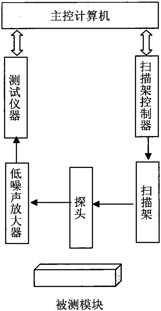
The present invention provides an electromagnetic radiation test-based microwave circuit fault diagnosis device, which comprises a probe, an amplifier, a test instrument, a scanning frame, a controller, a main control computer and the like. The probe is adopted as a near-field antenna and is arranged on the scanning frame. Under the effect of the controller, the scanning frame moves along the X-axis and the Y-axis to conduct the scanning operation. Meanwhile, electromagnetic signals radiated from a to-be-measured module are coupled onto the scanning frame. After the result of the scanning operation is amplified by a low-noise amplifier, the parameter measurement is conducted. The computer analyzes the result of the parameter measurement and then plots the electromagnetic radiation intensity distribution diagram of the to-be-measured module. The electromagnetic radiation intensity distribution diagram of the to-be-measured module is compared with the electromagnetic radiation intensity distribution diagram of a performance-normalized module, so that an abnormal region can be found out. After that, a possible fault point is derived reversely on the basis of the abnormal region. According to the technical scheme of the invention, the damage of hard contact to microwave multifunctional modules and the impedance-mismatching influence can be avoided due to the adoption of the electromagnetic radiation test. Meanwhile, the occurrence of mis-operations, such as the contact with a power supply and the like, can be avoided. Therefore, the test instrument is prevented from being damaged, and the diagnosis efficiency is improved significantly.

Description

technical field [0001] The invention relates to the technical field of testing, in particular to a microwave circuit fault diagnosis device based on electromagnetic radiation testing, and also relates to a microwave circuit fault diagnosis method based on electromagnetic radiation testing. Background technique [0002] Due to the working frequency band, the size of the microwave multi-function module is relatively small, and the structure is also relatively complicated. There are various types of performance indicators to be tested, and the fault diagnosis is also difficult. In the microwave multi-function module, it is not possible to directly lead to the test point like the analog circuit and the digital circuit. Therefore, test design circuits such as power division, coupling and detection must be added, but this often leads to the decline of the performance index of the microwave circuit. . Therefore, testability design is generally not or seldom carried out in the desi...

Claims


Application Information

Patent Timeline
Patent Type & Authority Applications(China)
IPC IPC(8): G01R31/28
Inventor 丁志钊夏磊刘伟张海庆王钊王金蒋玉峰杜雷
Owner THE 41ST INST OF CHINA ELECTRONICS TECH GRP
Why Eureka
Try Eureka