Electric field overhead line wireless energy taking device

A technology of overhead lines and energy harvesting devices, applied in the direction of electromagnetic wave systems, etc., can solve the problems of inability to obtain low-voltage energy sources and complicated power supply methods, and achieve the effects of simple structure, high reliability, and stable energy harvesting

Inactive Publication Date: 2015-11-11
STATE GRID CORP OF CHINA +1
View PDF4 Cites 3 Cited by
  • Summary
  • Abstract
  • Description
  • Claims
  • Application Information

AI Technical Summary

Problems solved by technology

[0003] The present invention aims to solve the problem that the existing online devices installed in a high-volta

Method used


Image

  • Electric field overhead line wireless energy taking device
  • Electric field overhead line wireless energy taking device
  • Electric field overhead line wireless energy taking device

Examples


specific Embodiment approach 1

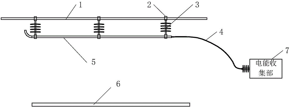
[0029] Specific implementation mode one: see figure 1 Describe this embodiment, the electric field overhead line wireless energy harvesting device described in this embodiment, it includes a receiving line 5 and an electric energy collecting part 7;

[0030] The receiving line 5 is located between the overhead ground wire 1 and the overhead wire 6, and the receiving line 5 is fixed at the lower part of the overhead ground wire 1;

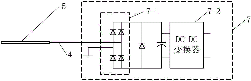
[0031] The receiving line 5 is rod-shaped, and one end of the receiving line 5 is connected to the power input end of the power collection part 7 through an insulated wire 4, and the electric energy output by the power output end of the power collection part 7 is used to supply power to the electric equipment, and the power collection part 7 shows The surface is connected to the ground, and the breakdown resistance of the insulating layer of the insulated wire 4 and the receiving wire 5 meets the highest ground voltage requirement.

[0032] In thi...

specific Embodiment approach 2

[0034] Specific implementation mode two: see figure 1 Describe this embodiment, the difference between this embodiment and the electric field overhead line wireless energy harvesting device described in the first embodiment is that it also includes a hanging wire 3, and the receiving wire 5 is fixed on the overhead ground wire 1 through the hanging wire 3 lower part.

specific Embodiment approach 3

[0035] Specific implementation mode three: see figure 1 Describe this embodiment, the difference between this embodiment and the electric field overhead line wireless energy harvesting device described in the second specific embodiment is that both ends of the hanging wire 3 are provided with ground wire clamps 2, and the two ends of the hanging wire 3 The ground wire clamp 2 is fixedly connected with the overhead ground wire 1 and the receiving wire 5 respectively, and the hanging wire 3 is made of composite insulating material.


PUM


Abstract

An electric field overhead line wireless energy taking device relates to a wireless power taking device in the technical field of power transmission. The problem that the power supply mode of an existing online device installed in a high-voltage environment is complex and low-voltage energy cannot be taken directly from an overhead conductor is solved. The electric field overhead line wireless energy taking device comprises a receiving line and a power collecting part. The receiving line is disposed between an overhead ground line and an overhead conductor, and the receiving line is fixed below the overhead ground line. The receiving line is rod-shaped, one end of the receiving line is bent towards the overhead ground line, and the other end of the receiving line is connected with the power input end of the power collecting part through an insulated conductor. Power output from the power output end of the power collecting part is supplied to electrical equipment. The surface of the power collecting part is connected with the ground. The electric field overhead line wireless energy taking device of the invention is mainly applied to high-voltage lines.

Description

technical field [0001] The invention relates to a wireless power-taking device in the technical field of power transmission. Background technique [0002] With the promotion of smart grid technology and condition-based maintenance technology, in addition to traditional power equipment, more information collection, transmission and processing devices will be added to the future power grid. Power equipment condition monitoring devices installed in high-voltage environments (strong magnetic field, strong electric field radiation) have powerful detection, data processing and communication functions, but the development of their power supply methods is relatively lagging behind. Although many field devices are close to the grid, they cannot directly obtain power from the high-voltage grid due to the limitation of the voltage level. It is difficult to find a suitable power supply entry point or feeding method, which has caused great obstacles to the application of power equipment...

Claims


Application Information

Patent Timeline
IPC IPC(8): H02J17/00
Inventor 于春来刘洋郭蕴朱学成张洪达张亮
Owner STATE GRID CORP OF CHINA
Why Eureka
Try Eureka