Method for manufacturing a fuel tank and fuel tank

A technology of fuel tanks, thermoplastic materials, applied in the direction of arrangement, application, household components combined with the fuel supply of internal combustion engines, capable of solving problems such as mass increase

Inactive Publication Date: 2015-11-11
KAUTEX TEXTRON
View PDF4 Cites 4 Cited by
  • Summary
  • Abstract
  • Description
  • Claims
  • Application Information

AI Technical Summary

Problems solved by technology

The additional requirements for improved stability and fire resistance inevitably lead to an increase in mass, which is actually undesirable for lightweight structures

Method used


Image

  • Method for manufacturing a fuel tank and fuel tank
  • Method for manufacturing a fuel tank and fuel tank
  • Method for manufacturing a fuel tank and fuel tank

Examples


Embodiment Construction

[0041] first refer to attached figure 2 .

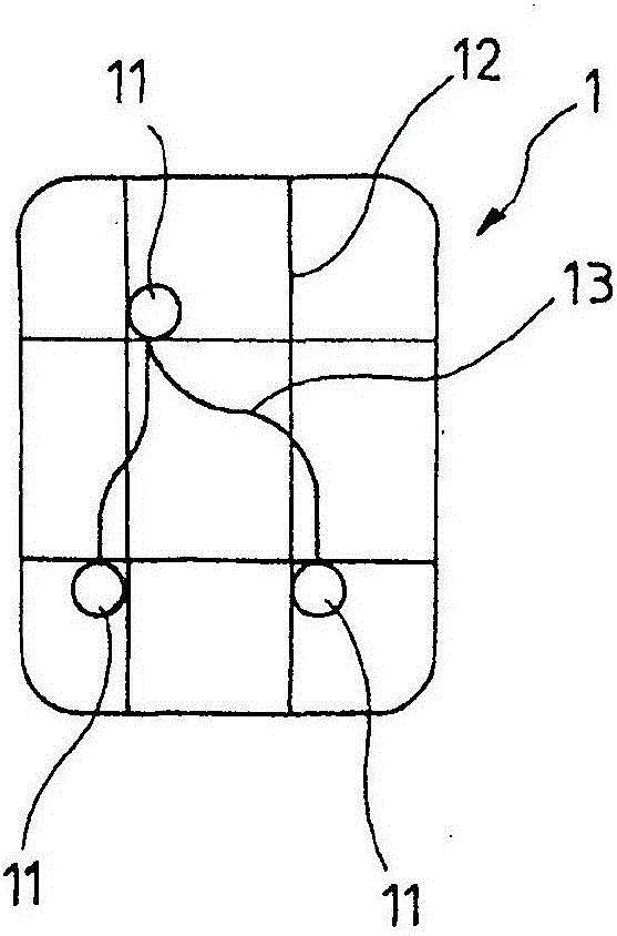
[0042] figure 2 A view of the upper casing 1 of the fuel tank according to the invention is shown. The fuel tank is joined together by an upper casing 1 and a lower casing 2 which complements the upper casing, forming a substantially closed hollow casing. A full view of the fuel tank is not shown in the drawings.

[0043] Both the upper shell and the lower shell have a surrounding flange 8 at which the upper shell 1 and the lower shell 2 are connected to form a closed fuel tank.

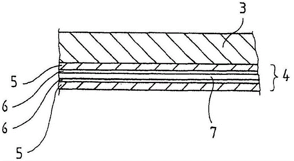
[0044] As stated at the outset, both the upper housing 1 and the lower housing 2 consist of a carrier material in the form of an organometallic sheet 3 and a laminate 4 laminated on one side (in the present case formed as a multilayer film) . The organometallic sheet 3 consists of, for example, an HDPE (high density polyethylene) base material / HDPE (high density polyethylene) base material and has embedded therein fibers in the form of carbon fibers,...


PUM

PropertyMeasurementUnit
Thicknessaaaaaaaaaa

Abstract

Method for manufacturing a fuel tank on the basis of thermoplastic material, comprising the following steps: • producing semifinished products (3) in sheet form from a fibre composite material with a matrix of thermoplastic material, • laminating the semifinished products (3) with a laminate (4) that comprises at least one barrier layer (7) for hydrocarbons, • heat-treating the laminated semifinished products (3+4) until the thermoplastic material plasticizes, • thermoforming the plasticized semifinished products in a thermoforming mould to form shells (1, 2) and • joining the shells (1, 2) to form an essentially closed tank.

Description

technical field [0001] The invention relates to a method for producing a fuel tank based on thermoplastic material. Background technique [0002] Fuel tanks of thermoplastic material are known, mainly made of polyethylene (HDPE), which generally have a multilayer wall structure with a barrier layer for hydrocarbons. Fuel tanks of thermoplastic material are known to be formed by injection moulding, extrusion blow moulding, or thermoforming, or a combination of these methods. Compared to sheet metal fuel tanks, thermoplastic material fuel tanks have the advantage that thermoplastic material fuel tanks can be produced relatively easily with spatially complex contours and are relatively more resistant to deformation and more stable. Plastics have a certain elasticity that enables thermoplastic fuel tanks to withstand short-term deformations, ie during which short-term deformations do not cause a permanent change in the profile of the tank. [0003] But due to the tendency of H...

Claims


Application Information

Patent Timeline
IPC IPC(8): B60K15/03B29C65/02B29C65/48
CPCB29C65/5071B29C65/02B29C65/1412B29C65/16B29C65/48B29C66/0324B29C66/1312B29C66/135B29C66/53247B29C66/54B29C66/55B29C66/71B29C66/721B29C66/7212B29C66/72141B29C66/7234B29C66/7392B29L2031/7172B60K15/03177B60K2015/03032B60K2015/03046B60K2015/0346B29C51/02B29C51/12B29C51/145B29K2023/065B29K2023/086B29K2105/08B29K2105/256B29K2277/10B29K2995/0069B60K2015/03493B29K2309/08B29K2307/04B29K2023/04B29K2023/0633
Inventor U·卡尔施
Owner KAUTEX TEXTRON
Why Eureka
Try Eureka