Spray coagulation and tiny dust removal system

A technology for removing fine dust, applied in the direction of steam condensation, separation of dispersed particles, chemical instruments and methods, etc., can solve the problems of secondary flying of fine dust, low dust removal efficiency of spray tower, excessive emission concentration of fine dust, etc. To achieve the effect of preventing secondary flying

Inactive Publication Date: 2015-11-18
CHINA HUADIAN ENG +2
View PDF2 Cites 1 Cited by
  • Summary
  • Abstract
  • Description
  • Claims
  • Application Information

AI Technical Summary

Problems solved by technology

However, due to the dust removal and environmental protection facilities such as electrostatic precipitator or bag filter in front of the spray tower, the particle size of the dust particles entering the spray tower is mostly below 20 μm, and the particle size of the dust is small, resulting in low dust removal efficiency of the spray tower. Can not meet the current requirements of the national environmental protection 10mg / Nm 3 emission requirements
Moreover, the top of the spray tower is equipped with a demister flushing system. The demister flushing system is flushed at least once every 8 hours, and the flushing time is longer than 30 minutes. As a result, the emission concentration of fine dust seriously exceeded the standard in some periods

Method used


Image

  • Spray coagulation and tiny dust removal system
  • Spray coagulation and tiny dust removal system
  • Spray coagulation and tiny dust removal system

Examples


Embodiment 1

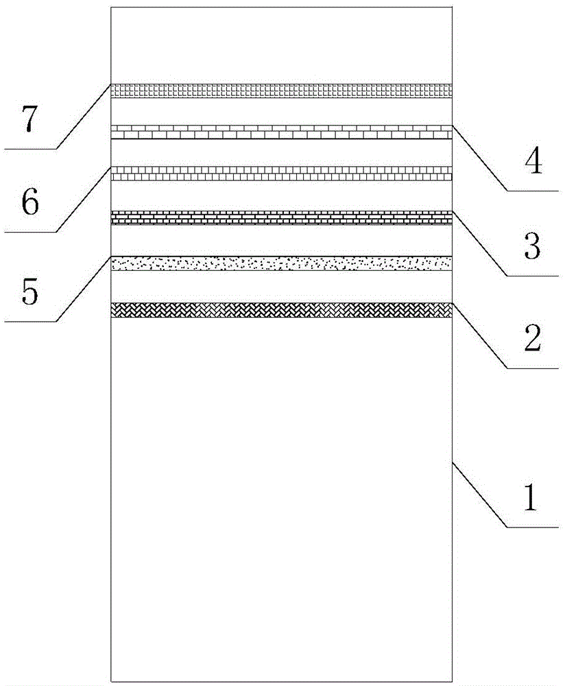
[0022] Embodiment 1 of the present invention: as figure 1 As shown, a spray condensate and fine dust removal system includes a first-stage turn-back type demist device 5, and the first-stage turn-back type demist device 5 is arranged in the spray tower 1, and the spray tower 1 is provided with a top The spray layer 2 and the first-stage turn-back demist device 5 are located above the top spray layer 2 .

[0023] It also includes a dual-fluid spray device 3 , which is located in the spray tower 1 , and which is located above the first-stage turn-back demist device 5 .

[0024] It also includes a second-stage turn-back demist device 6 , which is located in the spray tower 1 , and which is located above the two-fluid spray device 3 .

[0025] It also includes a condensing particle agglomeration device 4, which is located in the spray tower 1, and the condensing particle agglomeration device 4 is located above the second-stage turn-back demisting device 6.

[0026] It also inclu...

Embodiment 2

[0030] Embodiment 2: as figure 1 As shown, a spray condensate and fine dust removal system includes a first-stage turn-back type demist device 5, and the first-stage turn-back type demist device 5 is arranged in the spray tower 1, and the spray tower 1 is provided with a top The spray layer 2 and the first-stage turn-back demist device 5 are located above the top spray layer 2 .

[0031] It also includes a dual-fluid spray device 3 , which is located in the spray tower 1 , and which is located above the first-stage turn-back demist device 5 .

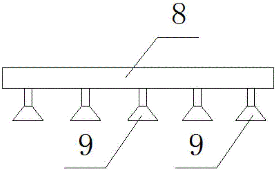
[0032] Such as figure 2 As shown, the two-fluid spray device 3 includes a pipe network 8 and a spray head 9 , the spray head 9 communicates with the pipe network 8 , and the spray head 9 is evenly arranged in the spray tower 1 .

[0033] It also includes a second-stage turn-back demist device 6 , which is located in the spray tower 1 , and which is located above the two-fluid spray device 3 .

[0034] It also includes a condensing p...


PUM


Abstract

The invention discloses a spray coagulation and tiny dust removal system. The system comprises a first stage reciprocating demisting device, the first stage reciprocating demisting device is arranged in a spraying tower, a top spraying layer is arranged in the spraying tower, and the first stage reciprocating demisting device is positioned above the top spraying layer. Power plant flue gas undergoes grading treatment in order to remove tiny dusts with large, medium and small particle sizes in the flue gas; and multi-stage reciprocating spraying devices are arranged in the system, so secondary flying of the tiny dusts is prevented, liquid droplets with the dimension being greater than 15[mu]m in the flue gas are removed, and discharge standards required by national environmental protection are reached.

Description

technical field [0001] The invention relates to the field of flue gas desulfurization and dust removal in thermal power plants, in particular to a spray condensate and fine dust removal system. Background technique [0002] At present, limestone-gypsum wet flue gas desulfurization technology plays an important role in the field of air pollution control in my country. The spray empty tower is the mainstream tower type of limestone-gypsum wet flue gas desulfurization technology, which has fewer internal components and is not easy to structure. Scale, high mass transfer efficiency and other advantages. The spray empty tower adopts large-flow spray washing to have a certain dust removal effect. However, due to the dust removal and environmental protection facilities such as electrostatic precipitator or bag filter in front of the spray tower, the particle size of the dust particles entering the spray tower is mostly below 20 μm, and the particle size of the dust is small, result...

Claims


Application Information

Patent Timeline
Patent Type & Authority Applications(China)
IPC IPC(8): B01D50/00B01D5/00
Inventor 李苇林沈煜晖沈国良赵凯
Owner CHINA HUADIAN ENG
Why Eureka
Try Eureka