Segmented expansion spring clamping device

A segmented, expanding spring technology, applied in the mechanical precision machining of long cylindrical thin-walled parts, segmented expanding spring positioning and clamping device field, can solve the problems of weak processing rigidity, and achieve improved processing accuracy and poor wall thickness. Uniform, reduced cutting vibration and deformation effects

Active Publication Date: 2017-09-12
江南工业集团有限公司
View PDF6 Cites 0 Cited by
  • Summary
  • Abstract
  • Description
  • Claims
  • Application Information

AI Technical Summary

Problems solved by technology

[0002] At present, when processing long cylindrical thin-walled parts, the internal expansion type centering spring is generally used to position and clamp the processing shape, which can better ensure the equal wall thickness of the workpiece and the coaxiality of the inner and outer circles. However, for high-precision large-diameter long cylinders For thin-walled parts, if the internal expansion type centering expansion spring positioning and clamping method is adopted, according to the working principle of the centering expansion spring, the expansion spring only supports the workpiece with inner cones at both ends, and the middle part is in a suspended soft clamping state, and the thin-walled workpiece The processing rigidity in the middle is still weak, which is extremely unfavorable for workpieces that require full-length wall thickness accuracy (wall thickness difference <0.05mm), and some designers even give up this positioning and clamping method

Method used


Image

  • Segmented expansion spring clamping device
  • Segmented expansion spring clamping device

Examples


Embodiment Construction

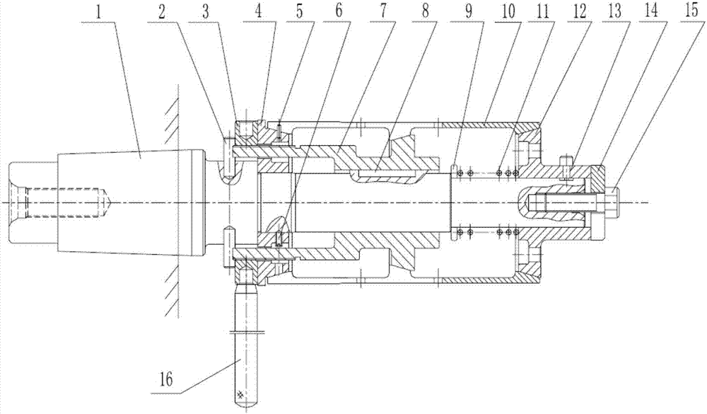
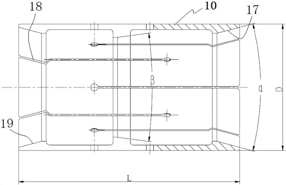
[0021] A bidirectional segmented expansion spring positioning and mid-section auxiliary support combined clamping device, such as figure 1 As shown, it includes main shaft 1, pin 2, nut 3, fixed cone 4, anti-rotation pin 5, stop screw 6, intermediate movable support body 7, key 8, adjusting washer 9, segmented expansion spring 10, spring 11 , Movable cone 12, limit screw 13, pressing plate 14, fastening screw 15, handle 16 and other parts. The structure is as follows: shaft 1 is connected with the inner hole of the machine tool spindle, and the fixture shaft is tightened with a long screw rod; after the 4 holes of the fixed cone are pressed into the shaft, it is fixed with the stop screw 6; one end of the segmented expansion spring 10 is placed on the fixed cone On the cone surface of the body, the opening groove on the expansion spring is aligned with the anti-rotation pin, and then the middle movable support body 7 is installed on the shaft, and the four bosses are aligned w...


PUM


Abstract

The invention discloses a clamping device with a sectional type expansion spring. The clamping device comprises a main shaft. The main shaft is fixedly sleeved with a middle movable supporting body and a movable cone capable of axially moving relative to the main shaft. The middle movable supporting body is sleeved with a fixed cone and the sectional type expansion spring. The outer wall of the middle movable supporting body is kept in contact with the middle section of the inner wall of the sectional type expansion spring. Inner cone holes are formed in the two ends of the sectional type expansion spring. An outer cone structure in cone face fit with the inner cone hole in one end of the sectional type expansion spring is arranged at one end of the fixed cone, and an outer cone structure in cone face fit with the inner cone hole in the other end of the sectional type expansion spring is arranged at one end of the movable cone, so that the sectional type expansion spring is evenly extruded when the movable cone moves towards the fixed cone in the axial direction of the main shaft. The means of sectional type expansion spring locating clamping, middle section auxiliary bearing and the like are adopted, and the machining precision requirements of long-barrel-shaped thin-walled pieces are further met.

Description

technical field [0001] The invention relates to a segmented expansion spring positioning and clamping device, which belongs to the technical field of mechanical processing, and is especially suitable for mechanical precision processing of long cylindrical thin-walled parts. Background technique [0002] At present, when processing long cylindrical thin-walled parts, the internal expansion type centering spring is generally used to position and clamp the processing shape, which can better ensure the equal wall thickness of the workpiece and the coaxiality of the inner and outer circles. However, for high-precision large-diameter long cylinders For thin-walled parts, if the internal expansion type centering expansion spring positioning and clamping method is adopted, according to the working principle of the centering expansion spring, the expansion spring only supports the workpiece with inner cones at both ends, and the middle part is in a suspended soft clamping state, and t...

Claims


Application Information

Patent Timeline
Patent Type & Authority Patents(China)
IPC IPC(8): B23B31/40
CPCB23B31/4026
Inventor 杨建贺杨昭张会茸常海苏瑜
Owner 江南工业集团有限公司
Why Eureka
Try Eureka