

Pipe assembly welding external clamping device
A technology for pairing and pipe fittings, applied in auxiliary devices, welding equipment, auxiliary welding equipment, etc., can solve the problems of low alignment welding efficiency and difficult control of welding quality, reduce skill requirements and labor intensity, and improve welding quality. , the effect of increasing friction
- Summary
- Abstract
- Description
- Claims
- Application Information
AI Technical Summary
Problems solved by technology
Method used
Image

Examples
Embodiment 1
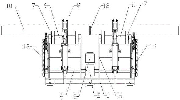
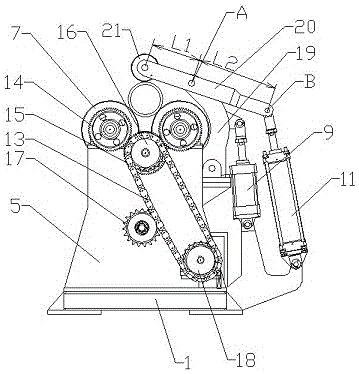
[0040] Example 1, such as figure 1 , figure 2 , image 3 As shown, a pair of pipe fitting welding external clamping device includes a base 1 on which two pair of pipe fittings 10 can be supported so that the two pair of pipe fittings 10 are located on the same axis and rotate synchronously. support device.
[0041] There are at least two sets of supporting devices arranged side by side. The supporting device is composed of at least two sets of rollers arranged side by side and capable of synchronous rotation, and the rollers of the roller sets are arranged coaxially;
[0042] Each set of roller sets includes two support rollers 7 arranged at a certain distance from front to back, and the support rollers 7 are connected to the power unit in transmission.
[0043] A compression device for compressing and fixing the pair of pipe fittings 10 is respectively installed at a corresponding position above each supporting device.
[0044] Several vertical roller frames 5 arranged ...
Embodiment 2
[0073] Example 2, such as Figure 5 As shown, in embodiment 1, the supporting rollers 7 near the front side are connected by the same connecting shaft 6 among the multiple groups of roller groups; the supporting rollers 7 near the rear side are also connected by the same connecting shaft 6 .
[0074] The power output shaft 4 of the reducer 2 is set as one, which is correspondingly driven with one set of support devices installed on the roller frame 5, and then the other set of support devices is driven to work synchronously through the connecting shaft 6, so that the pipe fittings can be assembled 10's of synchronous rotation at a constant speed.
[0075] In this embodiment, a set of transmission parts is reduced, the structure is simplified, and the cost is low. In the way of connecting the left and right support rollers 7 through a connecting shaft 6, there is no need to adjust the coaxiality of the left and right support rollers 7 during the installation process, which ensu...
Embodiment 3
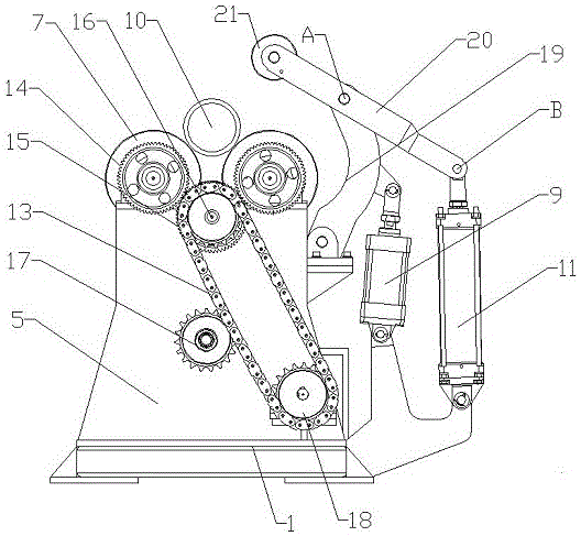
[0076] Example 3, such as Image 6 As shown, in Embodiment 1 and Embodiment 2, the compression rod 20 and the second pneumatic device in the compression device can also be removed, and only the crank arm 19 and the first pneumatic device are retained, and the pressure roller 21 is directly installed on the crank arm 19 The upper end of the upper end increases the curvature of the crank arm so that when it rotates to the support roller 7 around the lower hinge point, the pair of pipe fittings 10 can be compressed on the support roller 7.
[0077] In this embodiment, a set of pneumatic devices is reduced, and the purpose of the invention of pressing the paired pipe fittings on the support roller 7 can also be achieved, the structure is simplified, and the production cost is reduced.
PUM
 Abstract
Description
Claims
Application Information