Pressure reduction release eddy flow air floatation tank

An air flotation and tank technology, used in flotation water/sewage treatment and other directions, can solve the problems of easy blockage of dissolved air releasers, large floor space, low air flotation efficiency, etc., to achieve compact structure, reduced volume, simple structure

Inactive Publication Date: 2015-11-18
天津市振津石油天然气工程有限公司
View PDF4 Cites 6 Cited by
  • Summary
  • Abstract
  • Description
  • Claims
  • Application Information

AI Technical Summary

Problems solved by technology

Due to structural and design problems, traditional air flotation tanks and air flotation tanks usually have problems such as large footprint, easy blockage of dissolved air releaser, low air flotation efficiency, and complicated equipment.

Method used


Image

  • Pressure reduction release eddy flow air floatation tank
  • Pressure reduction release eddy flow air floatation tank
  • Pressure reduction release eddy flow air floatation tank

Examples


Embodiment Construction

[0024] The present invention will be described in further detail below in conjunction with the accompanying drawings and embodiments.

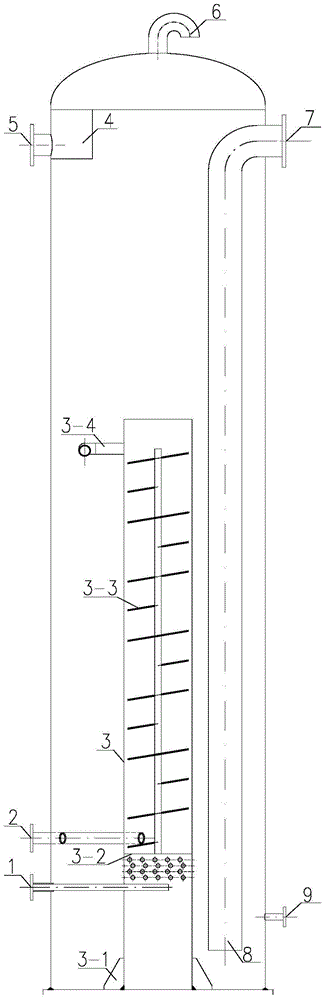
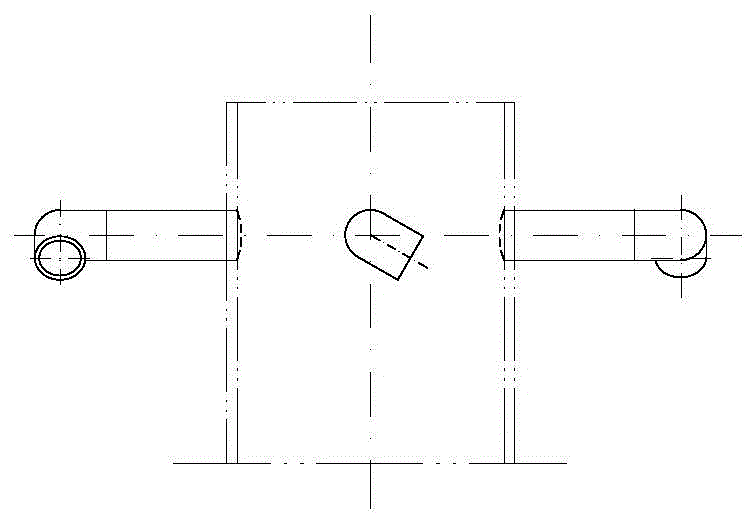
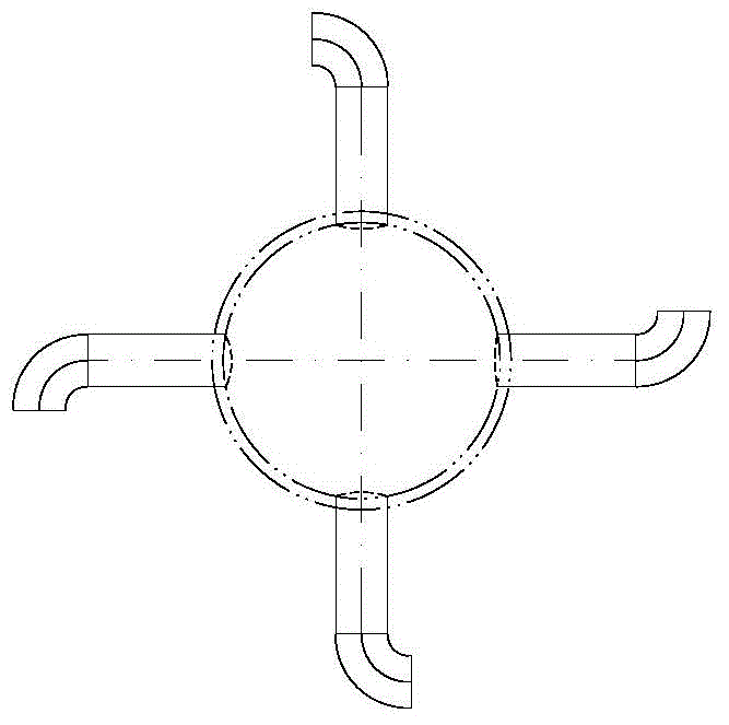
[0025] like figure 1 As shown, the tank body is provided with a dissolved air water inlet 1, a waste water inlet 2, a scum outlet 5, an exhaust port 6, a water outlet 7 and a return port 9; a central pipe 3 is arranged inside the tank, and the central pipe is perpendicular to the tank bottom, a support plate 3-1 is arranged at the bottom, a partition 3-2 is arranged on the central tube, blades 3-3 are arranged on the upper part of the partition, and the upper part of the partition between the lower part of the partition and the inlet pipe of dissolved air is arranged There are small holes; one side of the tank is provided with an outlet pipe 8, which is connected to the water outlet 7, and the upper part of the other side of the tank is provided with a scum tank 4, which is connected with the scum outlet 5, and the An exhaust pipe 6 is arrang...


PUM

PropertyMeasurementUnit
pore sizeaaaaaaaaaa

Abstract

The invention belongs to a pressure reduction release eddy flow air floatation tank. An air dissolution water inlet, a waste water inlet, a scum discharge port, an exhaust port, a water outlet and a backflow port are formed in a tank body. A center pipe is arranged inside the tank body and is perpendicular to the tank bottom, a supporting plate is arranged at the bottom of the center pipe, a partition plate is arranged on the center pipe, blades are arranged on the upper portion of the partition plate, and small holes are formed in the pipe wall between the lower portion of the portion plate and an air dissolution water inlet pipe. A water outlet pipe is arranged on one side inside the thank and connected with the water outlet. A scum tank is arranged on the upper portion of the other side inside the tank and communicated with the scum discharge port. An exhaust pipe is arranged in the center of a tank body end socket. A unique structure is adopted for the air floatation tank, and all functional zones are independent in position and are closely combined in treatment function, so that waste water and agents are mixed more fully under hydraulic power, and the utilization rate of the agents is increased. Under the action of an eddy flow field, the scum-water separation process is intensified, and the scum separation efficiency is improved. The air floatation tank is simple in structure, the size of the air floatation tank can reduced, and the air floatation effect can be improved.

Description

technical field [0001] The invention belongs to the technical field of wastewater treatment, and in particular relates to a novel decompression release cyclone air flotation tank for efficient treatment of oily and suspended solid wastewater. Background technique [0002] Air flotation is a method that uses highly dispersed micro-bubbles as a carrier to adhere to flocs in water, and relies on the buoyancy of the bubbles to make the buoyancy greater than gravity and buoyancy resistance, so as to realize the forced floating of flocs and achieve solid-liquid separation. A technology that can be divided into dispersed air flotation, dissolved air flotation, and electrolytic air flotation. Currently, pressurized dissolved air flotation is commonly used in the treatment of oily and suspended solids wastewater. [0003] The principle of pressurized dissolved air flotation is to dissolve air in water under pressurized conditions to form an air supersaturated state, and then reduce i...

Claims


Application Information

Patent Timeline
Patent Type & Authority Applications(China)
IPC IPC(8): C02F1/24
Inventor 钱哨唐思刘彪王文波武树霞
Owner 天津市振津石油天然气工程有限公司
Why Eureka
Try Eureka