Pressure trigger type underwater cast-in-place pile elevation locating device and using method thereof

A technology of underwater perfusion and positioning device, which is applied in the test of infrastructure, construction, infrastructure engineering and other directions, can solve the problems that the alarm accuracy cannot be guaranteed, there is no waterproof protection device, and the internal circuit is short-circuited. The effect of less quantity and less waste

Active Publication Date: 2015-11-18
SHANDONG UNIV
View PDF8 Cites 6 Cited by
  • Summary
  • Abstract
  • Description
  • Claims
  • Application Information

AI Technical Summary

Problems solved by technology

[0004] 1. The pressure sensor is a conventional model, which is not targeted, and is easily damaged during the concrete pouring process of the underwater pouring pile;
[0005] 2. The structure does not have a corresponding waterproof protection device. Under the special working conditions underwater, it is easy to soak in water, resulting in short circuit or even damage to the internal circuit;
[0006] 3. The traditional sensor is an electronic sensor. When a certain direction of the probe is subjected to instantaneous pressure, it will alarm. Therefore, it is impossible to avoid the one-way pressure trigger caused by the sudden upwelling of concrete caused by the vertical movement of the conduit, and the accuracy of the alarm cannot be guaranteed.

Method used


Image

  • Pressure trigger type underwater cast-in-place pile elevation locating device and using method thereof
  • Pressure trigger type underwater cast-in-place pile elevation locating device and using method thereof
  • Pressure trigger type underwater cast-in-place pile elevation locating device and using method thereof

Examples


Embodiment Construction

[0046] The present invention will be further described below in conjunction with the accompanying drawings and embodiments.

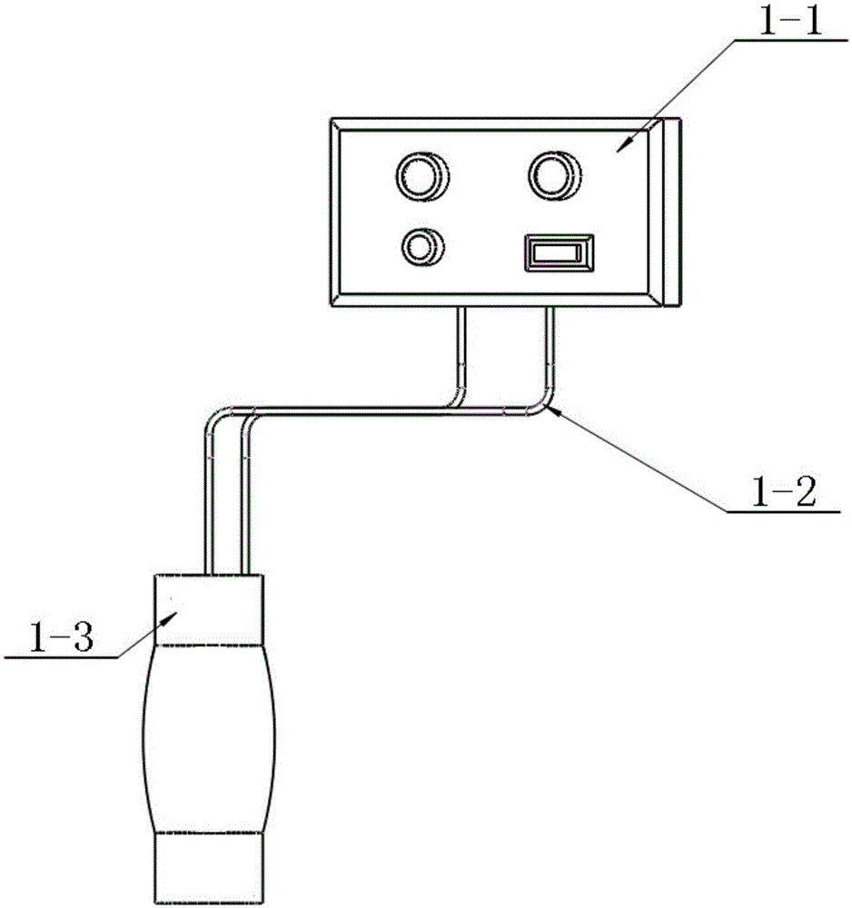
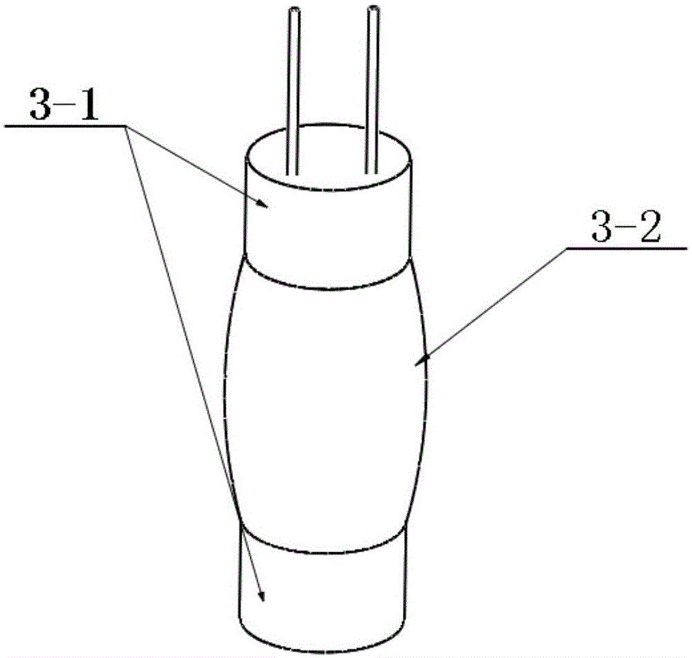
[0047] Such as Figure 1-Figure 5 As shown, a pressure-triggered underwater pile filling control device includes a hand-held buzzer and vibration alarm 1-1, a waterproof wire 1-2, and an underwater pressure probe 1-3. Wherein, the positive and negative pole inlets at the bottom of the hand-held alarm are respectively connected to one end of the two wires, and the other end of the wire is connected to the underwater pressure probe 1-3, and waterproof treatment is done.

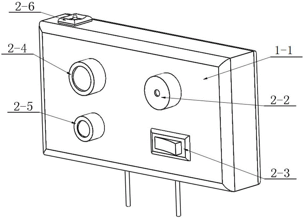
[0048]The hand-held buzzer and vibration alarm 1-1 is equipped with a working indicator light 2-4, a charging indicator light 2-5, a buzzer 2-2, a power switch 2-3, a built-in lithium battery and a built-in vibrator, There are charger connector sockets 2-6 on the top surface, and positive and negative pole inlets on the bottom surface, which can be connected with waterproof wires 1-2. ...


PUM


Abstract

The invention discloses a pressure trigger type underwater cast-in-place pile elevation locating device and a using method thereof. The pressure trigger type underwater cast-in-place pile elevation locating device comprises an underwater pressure probe, an alarm device and two waterproof wires, wherein the underwater pressure probe is connected with the alarm device in series through the two waterproof wires. The underwater pressure probe comprises a probe protection cover and a pressure sheet fixing bar which is arranged in the probe protection cover. Multiple pairs of outer pressure sheets and inner pressure sheets are fixed on the pressure sheet fixing bar, the outer pressure sheets correspond to the inner pressure sheets in position, and the outer pressure sheets are spaced from the inner pressure sheets by a certain distance internally and externally. The pairs of the outer pressure sheets and the inner pressure sheets are arranged in the radial direction of the underwater probe in an equal-angle mode. The outer pressure sheets and the inner pressure sheets are connected with the two waterproof wires respectively. The underwater pressure probe is placed at the pile foundation designed elevation position; when concrete rises to the designed elevation position, the concrete applies pressure to the periphery of the underwater pressure probe, so that the outer pressure sheets and the inner pressure sheets which are not closed originally are closed by bearing the pressure, a circuit is closed, and the alarm device connected with the circuit in series is excited by currents to work so as to give an alarm.

Description

technical field [0001] The invention relates to a pressure-triggered underwater cast-in-place pile control device and a method thereof, belonging to the field of construction engineering. Background technique [0002] Concrete is the most common construction material in civil engineering construction. It has a wide range of uses and plays an important role in the construction of buildings and the like. During the construction of underwater pile foundations, cast-in-situ piles often need to be poured in sections. However, in the staged pouring, due to the construction personnel's operation errors and various irresistible factors, it often occurs that the stage is overfilled, or the pouring does not reach the design elevation of the stage. In case of over-filling phenomenon, the soil body must be excavated after the pile foundation is formed, and the over-filled concrete must be chiseled off manually until the design elevation position at this stage, which will directly affec...

Claims


Application Information

Patent Timeline
Patent Type & Authority Applications(China)
IPC IPC(8): E02D15/06E02D33/00
Inventor 崔伟杨霓清高尚张乾青李宝金臧洪敏王术剑郑晓赵卫东孙朝阳胡继国吕高航
Owner SHANDONG UNIV
Why Eureka
Try Eureka