Multifunctional handle operating control system for loader

A control system and multi-functional technology, which is applied to earth movers/excavators, construction, etc., can solve the problems of increased labor intensity of operators, single function of joystick, and increased difficulty of operation, so as to improve operating efficiency and control The effect of simplicity and reduced labor intensity

Active Publication Date: 2015-11-18
XCMG CONSTR MACHINERY
View PDF6 Cites 6 Cited by
  • Summary
  • Abstract
  • Description
  • Claims
  • Application Information

AI Technical Summary

Problems solved by technology

[0003] Secondly, when shoveling the same material under the same working conditions, it mainly depends on the operator's technical level. The difficulty of operation increases, and the deviation is large, which is not conducive to energy saving and consumption reduction.
Even if the operator specifies the optimal height of the bucket for shoveling, lifting height, bucket discharge angle and optimal angle of the bucket during the operation, it cannot be accurately realized through control, so it can only rely on the operator's operating level
[0004] In addition, the function of the joystick of the current loader is relatively single. When the operator is operating the loader to perform joint operations, there are many joysticks or function buttons, and the operation is complicated. It is necessary to ensure the operation of the direction and the operation of the working device, and the function is single. The handle undoubtedly increases the labor intensity of the operator during the operation

Method used


Image

  • Multifunctional handle operating control system for loader
  • Multifunctional handle operating control system for loader

Examples


Embodiment Construction

[0025] The present invention will be further described below in conjunction with the accompanying drawings.

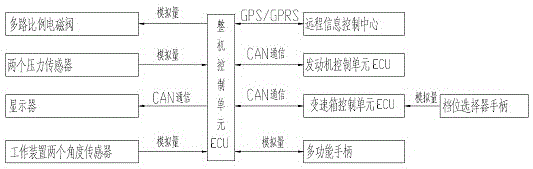
[0026] like figure 1 As shown, the present invention includes a complete machine control unit, and a remote information control center, an engine control unit, a gearbox control unit, a multifunctional handle, a multi-way proportional solenoid valve, a display, and a device installed on the working device. Two pressure sensors and two angle sensors, and a gear selector handle connected to the transmission control unit. The two pressure sensors are respectively installed at the oil inlet and the oil outlet of the hydraulic oil cylinder of the working device.

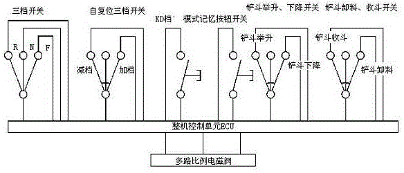
[0027] like figure 2 As shown, the multifunctional handle integrates a three-speed switch with direction gear function, a self-resetting three-speed switch with plus and minus gear function, a KD button with KD gear function, a mode memory button, and bucket lifting and lowering functions. The three-speed swit...


PUM


Abstract

The invention discloses a multifunctional handle operating control system for a loader. The multifunctional handle operating control system for the loader comprises a complete machine control unit, a remote information control centre, an engine control unit, a gearbox control unit, a multifunctional handle, a multi-channel proportional solenoid valve, a displayer, two pressure sensors, two angle sensors and a gear selector handle, wherein the remote information control centre, the engine control unit, the gearbox control unit, the multifunctional handle, the multi-channel proportional solenoid valve, the displayer, the two pressure sensors and the two angle sensors are connected with the complete machine control unit respectively; the two pressure sensors and the two angle sensors are installed on a work device; the gear selector handle is connected with the gearbox control unit; a three-way switch with the direction gear function, a self-reset three-way switch with the shifting-up and shifting-down functions, a KD button with the KD gear function, a pattern memory button, a three-way switch with the bucket lifting and falling functions and a three-way switch with the bucket unloading and taking-back functions are integrated on the multifunctional handle. The operation procedures are simplified, the memory pattern of the work device is achieved, and real-time monitoring of the complete machine operation conditions and establishment of a database are facilitated.

Description

technical field [0001] The invention relates to a multifunctional handle manipulation control system, which is especially suitable for loaders. Background technique [0002] The main working mode of the loader is the Y-type shovel-loading joint operation. During the whole process, the direction changes from forward to backward, then forward and then backward, and then turns forward to enter the next cycle. In this process, the operator not only needs to manipulate the steering wheel, but also needs to manipulate the gear selector. Even if the electronically controlled gearbox has the KD function, it needs to change direction 4 times. At the same time, in the process of reversing, a series of operation and use of the working device must be completed. The working device is leveled into the material pile, retracted, lifted, raised, and then unloaded, retracted, leveled, lowered, and entered In the next working cycle, this process needs to operate the working device 8 times, so...

Claims


Application Information

Patent Timeline
Patent Type & Authority Applications(China)
IPC IPC(8): E02F9/22
Inventor 李寒光邱楚然张永胜谢朝阳侯卓磊耿丽静徐标栗俊明
Owner XCMG CONSTR MACHINERY
Why Eureka
Try Eureka